Notes on LK-800 Linear
History
This linear was brought to Curacao by Radioteam Finland in 1990 and used since by PJ9JT. It came with the house.
Schematic
Click here for diagram of the power supply.
Photos (April 5, 2011)
Photo 1 Photo 2 Photo 3 Photo 4 Photo 5
16 November 2002
No RF output. Verified that QSK board, T/R relays, input network were all working OK. W0NB found one tube very loose in socket -- pins were not gripping and were corroded. Swapped this tube to the vacant socket that gripped better. Burnished the airflow directors and re-installed them to remove carbon traces and sewed top of chimney shut on unused tube location.
This amp needs one new tube socket for 3CX800A7 and a new tube. (Pins 1, 2, 3, 8, 9, 10, 11 are utilized and connected. 4, 5, 6, 7, and 11 are grounded.)
This amp performed 100% at 160 station for CQWW CW 2002.
New 3CX800A7 tube bought June 2003 transported by W0CG on 9 July 2003.
September 2005
One tube shorted plate to ground. Installed new 3CX800A7 with good result, full output.
March 2009
Would not turn on. Relay chatters loudly for a second, then nothing. Sometimes blows one primary fuse.
July 2009
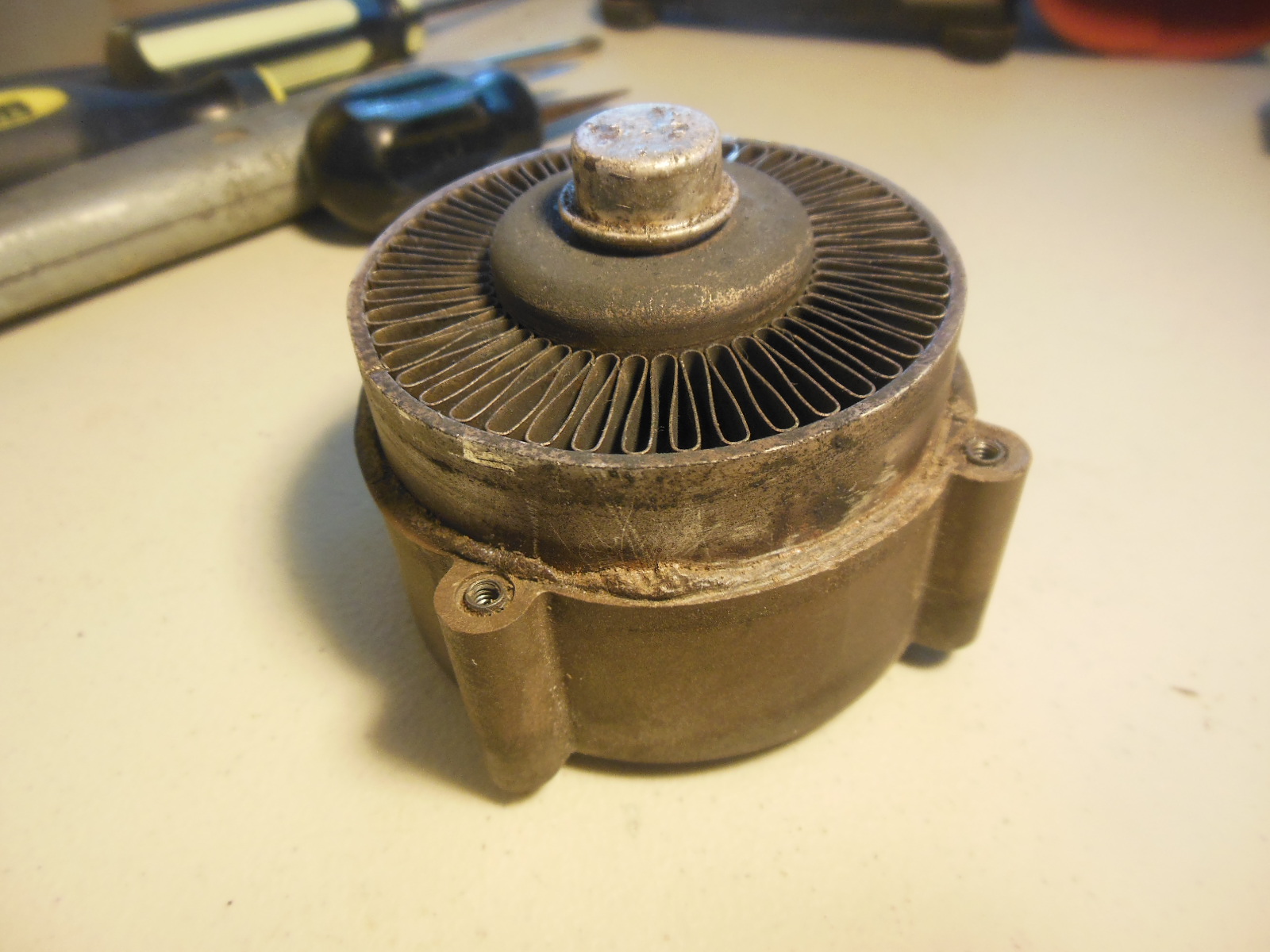
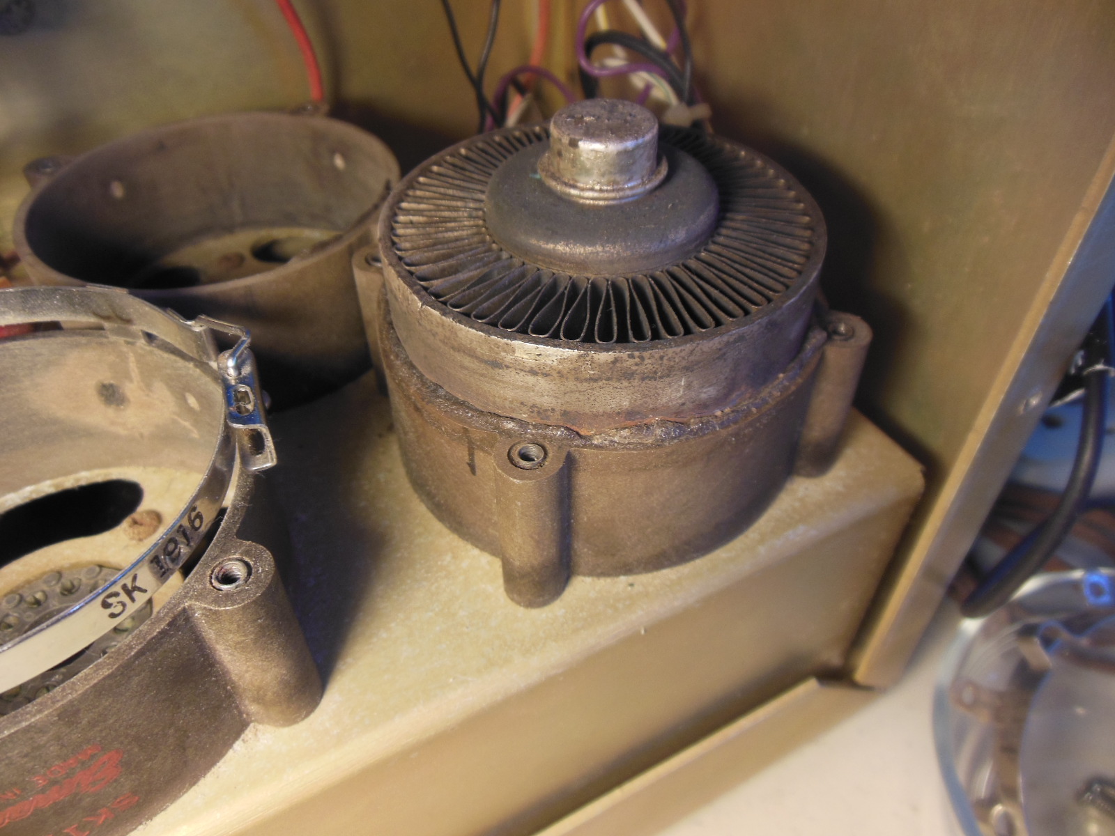
13-15 July troubleshooting by K8LEE with W0CG assisting. Lee found a screw in the power supply on one of the primary wires (black) to be a full turn loose. Tightening this probably solved all the problems. We cleaned the entire amp, reassembled, then the fan would not start. Replaced fan with a standard muffin fan, reassembled, all seemed to be OK. On air tests satisfactory.
Fan spec: German Pamotor Model 4600X, 115v, 50-60 Hz 20 watt. Mounting holes 10.5 cm on center, perfect square. ANY standard 4 inch muffin fan fits in this space.
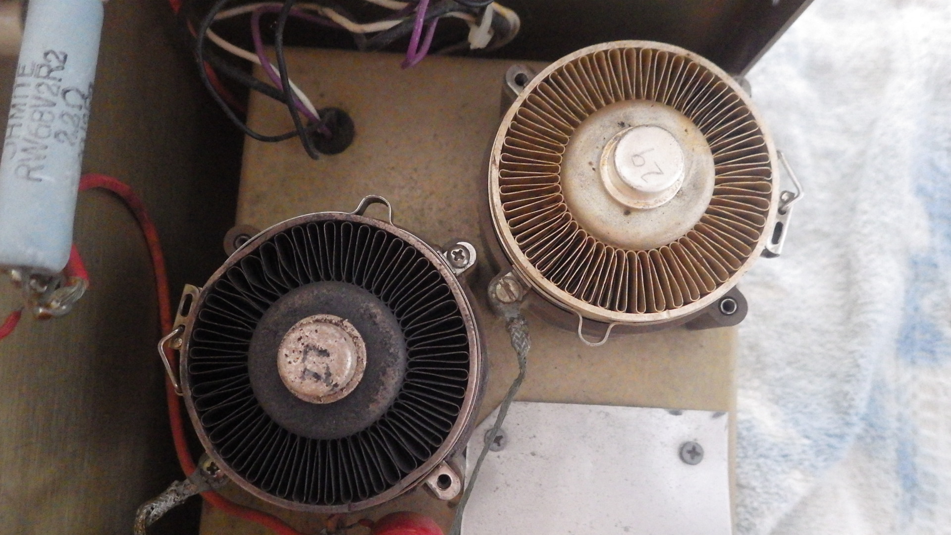
Tubes 27 and 28 in this amp were corroded but working OK after cleaning with alcohol.
October 2009
Fan would not start. Opened amp and pulled and reseated the board plug that runs the fan. Works OK now.
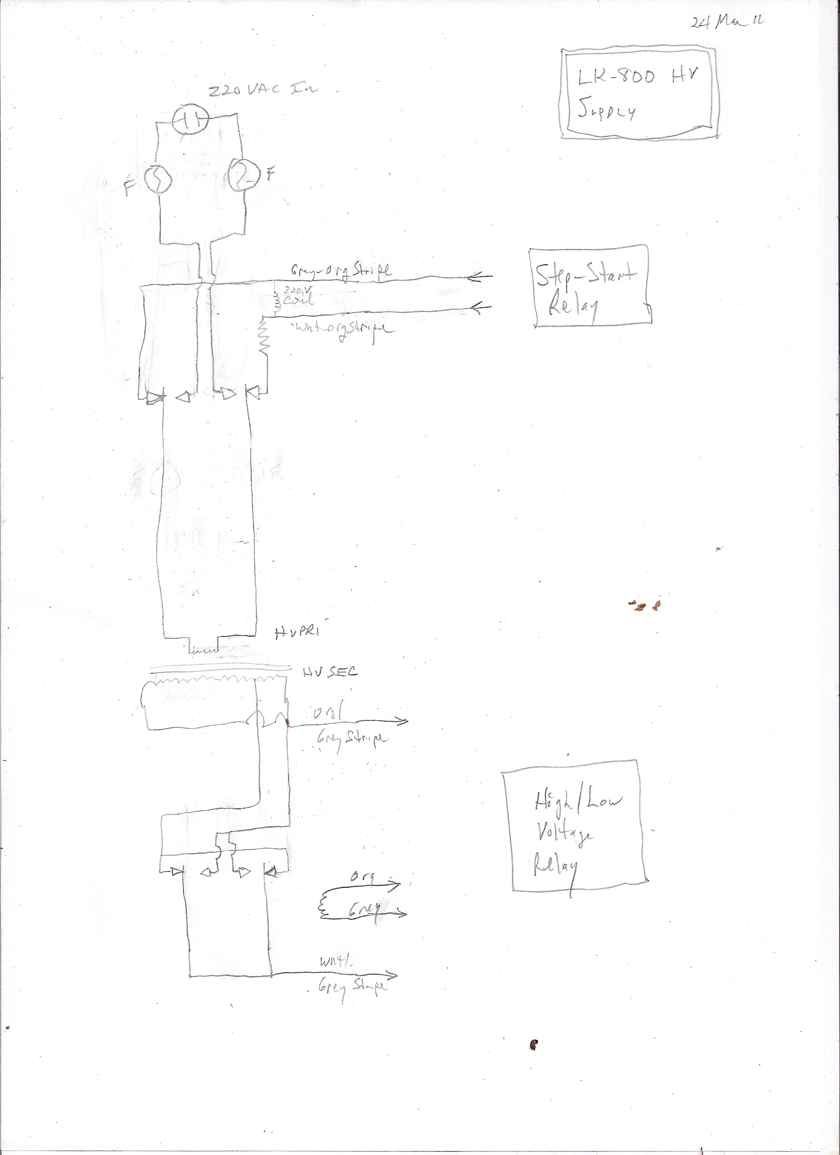
24 March 2011
California YLs reported intermittent, then dead. W0CG did troubleshooting and found an intermittent in the power plug going into the wall. Also created a schematic for the HV supply. Click here for that schematic. Click here for a photo. One relay is a step-start. 220V is initially applied to the HV primary through a composition resistor, and also directly to the relay coil, and as soon as that relay pulls in, the resistor is bypassed and HV power comes directly from the power cord to the power supply. Other relay selects high HV or lower HV for SSB or CW. Both relays are in corroded condition. Cutting out about 4 inches of teh power cords and reinstalling the plug corrected this problem.
5 April 2011
After replacing the power plug, discovered fan was dead. Troubleshooting revealed that the wiring in the plug that connects to the fan body (photo) was intermittent. Removed this plug and soldered directly to the pins on the fan. Still would not work. More hours of troubleshooting found bad long black wire in harness from the control board plug to the RF compartment. Pulled this out and replaced with new wire, re tie-wrapped, and all is now OK. On air tests revealed that RF output is down about 35%. About 1200 watts out on 15, about 1500 out on 40. Tubes look burned. Amp was run for an extended time without the blower operating.
22 October 2011
No output. All is OK with amp in standby. Suspect input relay. K8LEE troubleshooting. Wayne found visually that the middle Omron relay on the QSK board is not cycling. The other two on either side are fine. We re-soldered some questionable wiring on the QSK board, but still no luck - relay does not key. Troubleshooting confirmed that he coil in this relay was failed open. K8ND is ordering Omron G2VN-237P-US 12 VDC relay from PLCCenter.com to bring in November. Click here for the datasheet on this Omron relay.
19 November 2011
Replaced K2 on the QSK board with a new (used) Omron relay obtained by K8ND. The old relay tested OK, but after replacing the relay the amplifier came back up and worked fine. This leaves one spare new relay and the one that was removed, which has a broken plastic case.
January 2013
RF output only about half normal, more drive required, tuneup points slightly different. Suspect one bad tube. Troubleshooting shows tubes to be very badly burned and bottom phenolic chimney of right tube to be partly melted such that can't get the tube out without cutting it out of the plastic. Amp has run very, very hot without a fan.
7 February 2013
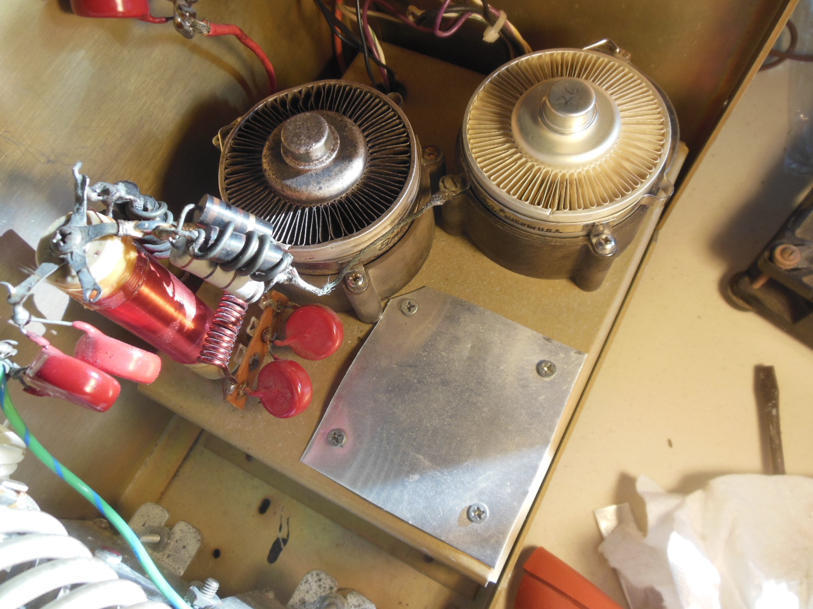
W0CG removed one burned hot looking tube (the one closer to the power supply side.) Could not remove the other one because the tube was fused to the phenolic chimney bottom from excess heat when amp was run for long period without fan. Thus removed the entire tube and chimney base assembly, fused together as one unit. Then moved the good chimney base from the unused socket to the right rear socket. Fabricated a sheet metal block to cover the unused tube socket. Installed Tube 26, a mostly new 3CPX800A7 in the right hand socket and reinstalled the older tube in left socket. Photo1 Photo2 Photo3 Further testing on 10 February revealed good (2 KW) output on all bands except 80 and 160, where output is not quite 1 KW with very heavy drive and the plate control seems to be very low Q. Something is wrong in the tank. Also discovered that output is higher on 15 when band switch is in 17 meter position. Put amp aside for ARRL CW contest and brought in an AL-1200 for the weekend. Further troubleshooting this date showed that low output problem on 160 and 80 is because the XCVR (FT1000(5)) was making only about 20 watts out on those bands. Slightly more on other bands.
28 February 2013
Tested with a good XCVR as a driver and get full 2KW output on all bands. Back in service at Station 3.
1 February 2014
Fan went inop in December as reported by K8ND. Opened up amp and tested for blade rotation. Blades were free. Lubricated shaft. Fan started and ran normally. Made several QSOs and ran amp all day at idle. All works perfectly.
22 February 2018
Troubleshooting, W0CG and KB7Q. Remover right hand tube (26) with result of 1000 watts output, same operation we have been seeing for a couple of years. Left hand tube is fused to its chimney, so leave it there as it makes good output. When tube fails in future, we have a new chimney for it.
23 February 2018
Amp has been running fine at 1 KW but not able to make any more power than that. After much experimentation and tube swapping, W0CG and KB7Q ended up with tube 29 in the right socket (taken from Titan 425) and left tube 27 in the left hole. Tube 27 is fused to its chimney. At low plate voltage of 2400 or so volts the amp easily makes 1800+ watts with low grid current. The plan is to leave tube 27 and its chimney in the amp until it fails completely. This is the tube configuration for this amp going forward.
The fan was inop. We took it out and swapped in a 110 VAC muffin fan that works but does not seem to move much air.
Thoroughly cleaned and dusted in the case and also sandpapered connector to the power supply and the inside of the overheated chimney.
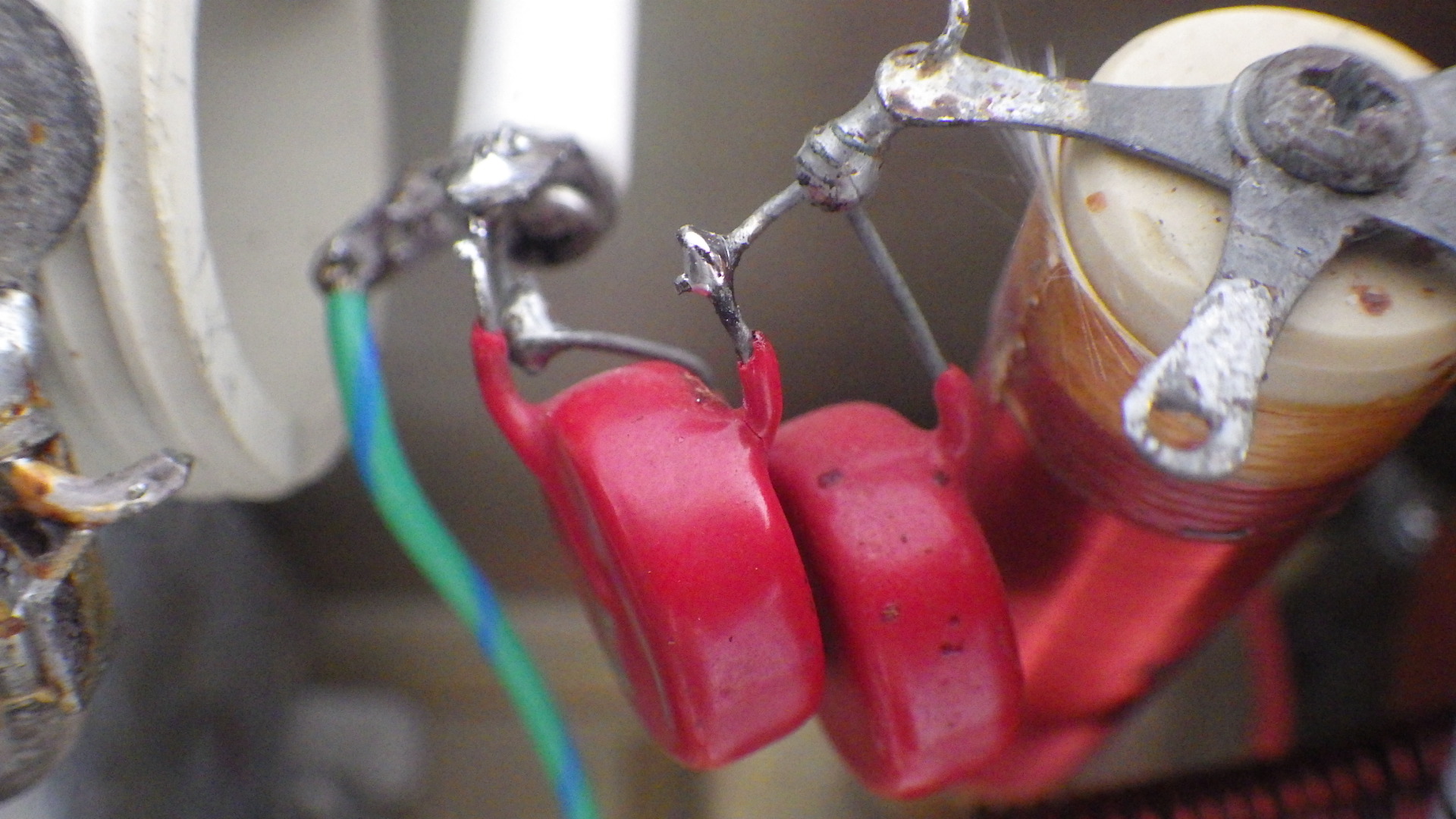
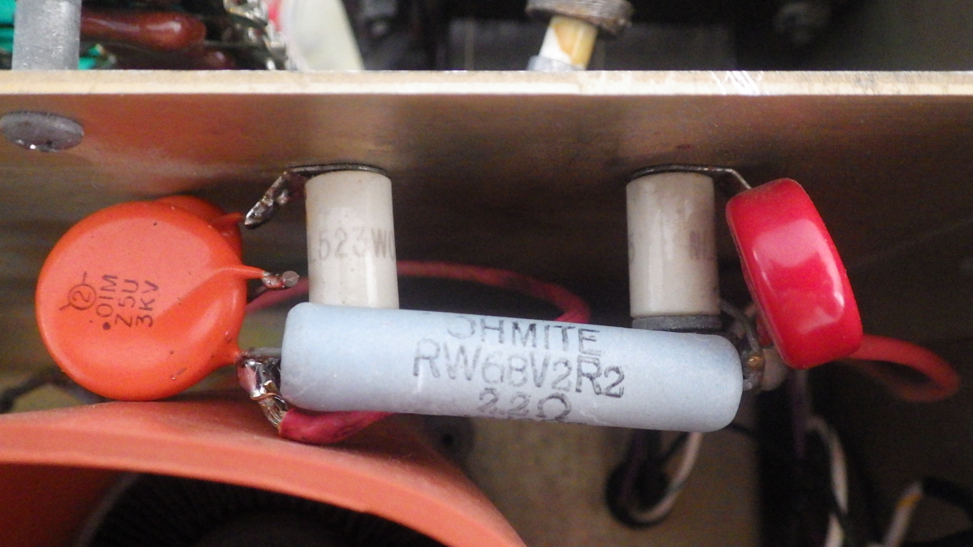
In doing this work one lead of the two plate feedthrough caps broke at the top of the plate choke. These are labeled 1000M 10KV.
24 February 2018
Bought new Eimac SK-1906 chimney via EBay, to arrive no later than March 15 to Idaho. This will be used when the fused tube/chimney in the left side finally fails.
To repair the broken feedthrough cap, I cannibalized an identical cap from the 2.2 ohm resistor in the RF case and installed that at the top of the plate choke (first photo). Then in place of the cannibalized bypass cap put in two .01 ufd 3 KV caps from the N1ZZ box in series (second photo).
Amp came on immediately when plugged in with HV and loud AC vibration. Will troubleshoot later.
1 Mar 2018
W0CG traced the above problem to one side of AC to the fan in contact with the chassis ground. Fixed this and reassembled amp. Good airflow now. Ran up to 800 watts on 40 meters and there was a big spark from top of plate choke and then grid current was very high. Probably lost one or both tubes to a short, tube failure, or parasitic oscillation. Will troubleshoot further as time allows. Need to replace the .01 series bypassed caps in photo above with correct matched caps in Fall season.
9 Mar 2018
Troubleshooting showed HV was off, and grid current of course high. HV supply fuse blown. Traced problem to black low voltage wire in contact with the exterior of the right tube. Moved wire away and taped it off, replaced fuses, and all appears to work OK. Amp is making 1700 watts easy with about 45 watts drive, very low grid current. W0CG and KB7Q troubleshooting. Will leave amp in place at Station 3,