Notes on Titan I (425) Linear
March 2005
Bartered from VERONA in exchange for Centaur, 811A tubes, and $500 cash.
Installed new AC power cord, cleaned, tested OK with about 1/2 output, but became inop after about an hour of use. Fan would work only on slow speed, and there was a hot formvar smell whenever the amplifier was turned on.
2 April 2005
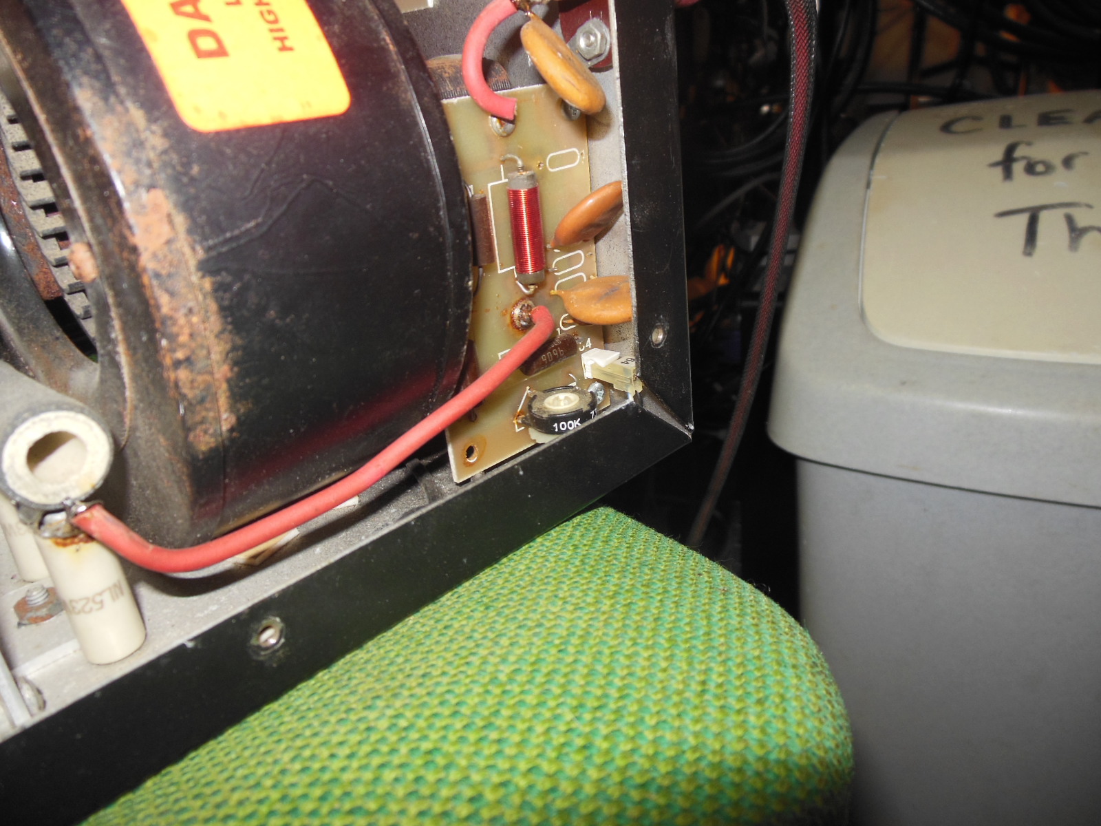
Cleaned rust particles from bottom of RF compartment. Blower housing is rusting. Tank coil is loose -- replaced a missing bolt in the bottom. The burning component is a resistor on the "Display" board -- 1 2 watt red black black gold; it reads 145 ohms on the meter. Found one wire broken off fan speed switch -- reconnected and now it is totally dead.
April 2005
Transported to the U.S. by W0CG and then drove
to Tennessee
and dropped it at the Ten-Tec factory for service on 21 April.
They found several bad components on the bias board, did the repair, and
did a full power test with their shop tubes and all looked OK. They shipped back
to me and I brought it to
November 2005
The
power supply was still suspect, and when I fired it up today for the first time
since the repair, the fan was still inop. I worked all day on this (16 November)
and found that one of the wires running to the fan speed switch in the power
supply had broken off and contacted the case, making quite a weld mark and doing
who knows what else on the AC Board in the power supply. I traced out all the
wiring with the schematic they gave me at the factory, reconnected the switch,
and darn, the fan was still dead.
They
use a strange arrangement to control the fan speed, switching in a small winding
on the transformer out of phase to buck down the 110VAC running to the fan.
Further diagnosis and testing verified that the fan was good, and it appears
that a domain on the AC Board in the power supply got burned out when the wire
came loose and hit the inside of the case, making the weld mark. So I tore into
the fan control circuit and did a fairly extensive modification (next
paragraph), bypassing the
fan speed nonsense circuitry and feeding 110VAC directly to the fan, tapping it
from the switched side of the 220 and ground in the power supply.
Red (Fast speed) wire was broken off lug of Fast/Slow switch. Repaired by adding blue wire connected to red one with a lug nut. Above did not work, so I took the red wire off the fan speed switch and wired it to ground - this goes to Pin 6 of the cable, then to the fan. Then cut the blue wire and soldered it to lug on K to provide one hot side of switched 220. Put crimps or wire nuts on all loose ends. (16 November 2005)
That
worked, and the amp is now operational, making about 2/3 output with the old
VERONA
tubes. I was able to get 1400 watts out on 15 without even trying hard. I
suspect it will do a lot more on the low bands.
I put rubber feet (photo) on the Titan I power supply today � half of them were missing. Go figure.
Photos of power supply caps and specific part numbers.
Late November 2005
In CQWW CW may be imposing buzz on transmitted signal. Acquired new set of power supply electrolytics December 2005 for transport to Curacao.
12 February 2008
N0YY and W8AV replaced electrolytics. Hum is now completely gone. Amp worked fine in service for a week at Station # 1.
30 March 2008
Placed in service at Station # 4.
25 November 2008
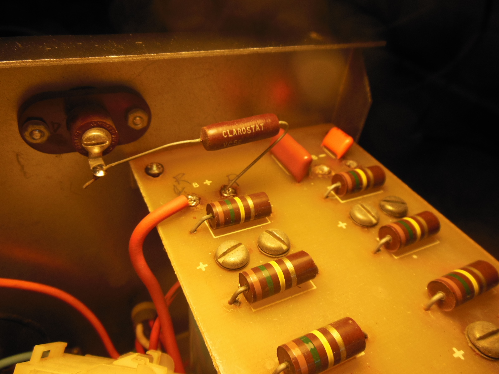
Turned on amp on an extremely humid day with heavy rain outside. Big pop, blew one primary fuse. Replaced fuse and amp is still dead. Found four series resistors on HV board all open, one physically blown. These are on order. Each is 47 ohms @ 25 watts = 12 ohms total. This is the primary surge resistor. The in line 4 amp slow blow fuse nest to the resistors did not blow. All diodes and electrolytics test OK. K8ND has diagrams on his laptop. Awaiting parts from Ten-Tec and N1ZZ. Will order several spares.
6-7 February 2009
W0CG installed four new 47 ohm 25 W resistors in the primary line of the transformer.
Procedure to Disassemble: Unsolder the B+ lines, two red, from top of filter cap board and label the wires. Take out four screws at corner of the filter cap board and set aside. Slide filter board up and out of case through the slots in side of case at top, then unsolder orange and red wires from bottom of filter cap board labeled O and R. Remove the filter caps completely from the power supply. Unplug four Molex plugs from transformer including one on the board itself. Get under the case and remove three nuts and then the long screws from the top of the diode board. the board can then be lifted up and worked on.
Further testing showed 300 ohms (!) from B+ connector on R deck to ground. Problem was traced to meter shunt board, which had C4 (.002, 6KV) physically blown and was showing DC resistance. Removal of this cap got rid of the 300 ohms and shows infinity now from B+ to ground.
Procedure to Remove Meter Shunt Board: Unscrew B+ from back of Millen HV connector. Unsolder red B+ wire from RF choke. Remove two screws (self-tapping) from back of amp case. Remove screw and nut from bottom of Millen HV connector. Unplug 64 going to meters and remove board.
Test of the amp with the B+ wire NOT connected to the RF deck resulted in no problems. Connected HV line and amp still appears to be OK. Put in screws and moved to Station # 1 and amp was dead -- would not start. Investigation showed that the power supply case screw at the interlock was strippd and the interlock was not closed. Replaced screw and amp started OK. Ran 30 minutes of QSOs on 20 CW with huge pileups and amp running cool.
NEEDS: ASAP replace the four 47 ohm 25 watt resistors with a 10 ohm 25 watt and put in the missing .01 6 K ceramic cap on the meter shunt board. Parts are on hand from N1ZZ in the Titan I box on the Radio Closet shelves.
5 December 2012
Amp blew fuses in October CQWW SSB startup. Today WX0B found a blown .002 bypass cap on the meter shunt board. It measured 8K so we cut it out of the circuit. Tested all diodes and HV caps good. Replaced 4A slo blo fuse in power supply. Cleaned tubes. Tested amp and it starts OK but no HV indication. Moved the pot on the meter shunt board and the HV indication returned. In power supply box, I replaced the red wire from the B+ board to the output HV connector with a 3 ohm resistor on advice of WX0B. This will serve as a fuse and will protect the diodes. The old red wire is tie wrapped to the transformer. Amp works correctly on the air. Replaced at Station 4.
22 November 2013
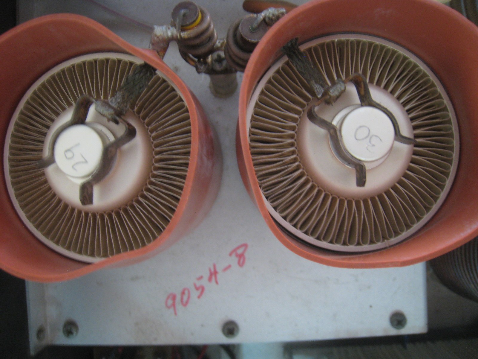
Amp suddenly started pinning the grid current meter when driven with only a watt or two. Replaced the rear tube with tube 29. That gave us 1000W of output, but not more. Replaced front tube with tube 30. Now amp makes full output, about 1500W per the front panel LEDs. Both of the old tubes (33 and 34) put into blue box storage.
Photo below shows RF deck after tube replacement on 22 November 2013. (Left is the rear of the amplifier.)
31 March 2015
Placed in storage after many good contests at Station 4, 20 meters. All working fine.
12 February 2016
Amp performed flawlessly in Fall season contests. Upon my return in February only half output was available. Strong indication is that one tube has failed. With careful tuning I can get about 1 KW output.
14 February 2016
This date W0CG did a series of tube swaps to try to diagnose the Titan 425 problems.
* Removed tube 29 (rear) - only
600 watts out with 30 watts drive
* Removed tube 30 (front) and put 29 into the front socket - amp shuts off at
end of wait period
* Put tube 30 in front, left the rear empty - got 600 w out; amp shut off
spontaneously; reseating the power plug in rear fixed this
* At this point tube 29 works in both holes, about 500 w out, thus eliminating a
possible problem with one or the other holes; K3 sees high input SWR with only
one tube in so it folds back output
* Put tube 34, old 1/2 good one from the Titan 425, into rear, tube 29 in front
- acceptable output of about 1300 watts on 80 and 20; did not check any other
bands; end of troubleshooting for now.
Also this date put a new 1820 pilot bulb in the right side meter. Works fine.
24 February 2018
Initially this amp had Tube 29 in the front, Tube 34 in the back. 29 alone made 700 watts LV and 1300 watts at HV. Tube 34 alone made 500 watts at LV, and we did not test it at HV.
Tested all 3CX800A7 tubes this date, using the rear socket in the Titan 425. After testing, selected Tube 26 for rear socket and Tube 22 for front socket. With low HV amp makes 1100 watts with low grid current, and at high HV output is over 1600 watts. Tube 26 is healthy, full output 1400 watts at low voltage; tube 22 is older, 600 watts at low voltage, and we would like to get all we can out of it as it wears out. Over time as amp starts to fail, replace the front tube, Tube 22 first.