Notes on Titan III Linear
Bought new by W8TK 26 August 2004
2 June 2006
Provided to CCC by W8TK. Handed off at Lexington, Ohio that date.
13 June 2006
Tested on the air at W0CG -- 100% successful. Transformer removed for transportation to Curacao.
20 June 2006
HV transformer transported to Curacao by W0CG and stored in right closet, West bedroom.
19 October 2006
Transported to Curacao by W0CG. Used the white case from Noel with some internal pads replaced and or modified. Paid about $138 duty. Paper is filed at W0CG in "CUR-Customs Papers." Assembled amp and initially it was dropping out of transmit after about a minute of foot switch key down, even without RF. W4PA found a loose connector from the screen board to the "Standby/Operate" switch and reseated it and the amp ran 100% perfectly through CQWW SSB at Station # 1.
5 March 2007
Amplifier was on, idling, when a power failure occurred. When power was restored had no RF output, but all other meter indications were normal. Cindy and W0CG found P20 burned, same as in Titan II, and the control grid bias line was open as indicated by VOM. Having no replacement jumper, I hard-wired the four lines to the board pins. Two filament. one screen bias, one control bias. New P20 jumper is on request from Ten-Tec.
20 October 2007
Took out of closet and placed in service at Station # 1 after carefully cleaning and inspecting the RF deck. Three days later, after about 2000 QSOs by W0CN, failed hard with no RF output. Wiggled and cleaned P20 with sandpaper and amp returned to life. Then on Sunday of CQWW SSB the weekend following, it failed the same way. K1XX, K1EA and I replaced the jumper with hard leads and amp appears to be 100% OK now. Ten-Tec recommends NOT replacing P20 with a new one -- it will fail also.
During CQWW SSB we had two power failures and amp was suddenly off after running hard. Had to replace both 20 amp grey ceramic line fuses, but all seemed OK after that.
17 November 2007
Titan III was arcing now and then apparently in tube compartment and blowing one of two main fuses. W0CG and K8ND discovered that in the left tube as viewed from front, the anode ring had fallen down inside the chimney and was arcing and welding to the chassis. Burned black on chimney. Cleaned all parts and repositioned anode strap and problem was gone.
20 July 2008
Severe arcing on 20 meters above 300 watts output was found to be caused by a large blister on loading capacitor. Filed it clean with an emery board and cleaned rest of capacitor and all is OK now at full power.
22 January 2009
Prior to CQWW 160 CW T/R relay was hanging in TX at the end of a transmission. It was necessary to turn the operate/Standby switch off, then back on to release it. Amp was taken out of service and used LK-800 for the contest.
9 February 2009
Replaced QSK board and problem went away. Will send QSK board to States with someone from ARRL DX CW contest and hopefully have it back here with someone from WPX SSB.
14 April 2009
W0CG has possession of a new QSK board and the old unprepared one in Idaho. Will take to Curacao when able. Click here for Ten-Tec invoice.
July 2009
New QSK board and old unrepaired one placed in blue bins. Amp worked perfectly for IARU contest. Moved to closet into backup until CQWWSSB.
29 October 2010
After several days of success on the air after coming out of the closet, amp failed at turn-on, blowing internal low voltage fuse. Troubleshooting by N8NR and K6AM concluded that T2, the low voltage transformer, had gone shorted. New transformer ordered 1 November by K8ND, $73.Jeff will take it to Curacao in November.
4 November 2010
Transformer replacement received from Ten-Tec at K8ND was labeled "MCI Limited P/N 51791 07/27" and has secondaries of 350V, 70V, and 12.6V.
Late November 2010
K8LEE and N0YY replaced screen transformer successfully. Amp working fine. But halfway through CQWW CW it failed. K8LEE diagnosed bad T/R relay. N4RV ordered a replacement relay and brought it to Curacao 7 December 2010.
11 December 2010
W0CG replaced the T/R relay. Amp now appears to work 100% fine. This relay is mounted on a sub-board that is soldered to the SWR board, which is in the bottom of the amp. This board is removed by taking the four screws out of the SO-239 in and out jacks on the back. Relay is in the same case and has the same pinout as the two relays on the T/R board in AL-1000 (2). RTE24012, 12 VDC, 30 AMP. Click here for parts invoice from Ten-Tec. (The SWR board is no longer available from Ten-Tec.)
12 December 2010
The removed LV transformer tests good with no load applied. I put it in the radio closet with a note.
22 March 2012
HV arc on turn-on and one side of primary fuse blew. Cleaned interior and next time it blew worse. Found that in the left chimney the anode strap was arcing to the chassis and there were burn marks on both. Removed tubes and still had big arc and fuse blew. Next need to try to remove chimney and see if arc stops. Chimney may have permanent conductance path to the chassis. Tubes appear to be OK. Left tubes in chimney but not in sockets, most screws in plastic bag, chimney straps taped in RF compartment when departed on March 24.
4 Sept 2012
Ordered two new chimneys from Ten-Tec to be shipped to Idaho address. See this document for the invoice.
5 Dec 2012
WX0B hard wired from screen board to next board and to tube socket. Removed the board to board plug connector. Still arcs in left tube socket at turn-on. Probably a bad tube socket. After more study and two days WX0B found that the problem was on the HV board in the RF deck that hosts the parasitic suppressors and the anode leaves to the tubes. There was an arc path from the B+ to ground over a spacing of less than 1/8 inch. Bad design. There was a burned trace in the board. He drilled out the offending part, creating an air barrier between HV and ground. We also hard wired the filaments and screen from board to board and eliminated the problem connector with very close spacing. Ugly, but it works. See photos. Left out HV crowbar and the tube straps. Put in the old chimneys. HV comes up normally now. Tested at Station 1 but no RF output. Also have no indication of RF on LEDs when run 100w of RF through the amp in through mode. Suspect T/R reed relay on SWR board.
11 January 2013
Ordered two K1 reed relays (pn 32049) and two T/R relays (pn 32101) direct from Ten-Tec to Idaho address. $46.80. Click here for invoice. Relays brought to Curacao by W9VA February 2013.
27 February 2013
K8LEE replaced input reed relay and same symptoms -- no grid current and no RF output. Further troubleshooting by K6AM and K8LEE found that WX0B had wired the tube sockets incorrectly. K6AM fixed all and dressed up the ugly wiring and now all is good. Amp returned to service at Station 1 on 27 Feb.
March 2013
Amp failed during casual operation. High SWR from the XVCR into the amp and RX down something like 60 dB. Traced problem to SWR board, and brought it to Idaho 10 April 2013.
25 April 2013
Shipped SWR board to K6AM for possible repair.
5 September 2013
W0CG brought the repaired board to Curacao. No time to install and test it in the amp. Board stowed in Radio Closet with label on the cardboard box.
2 December 2013
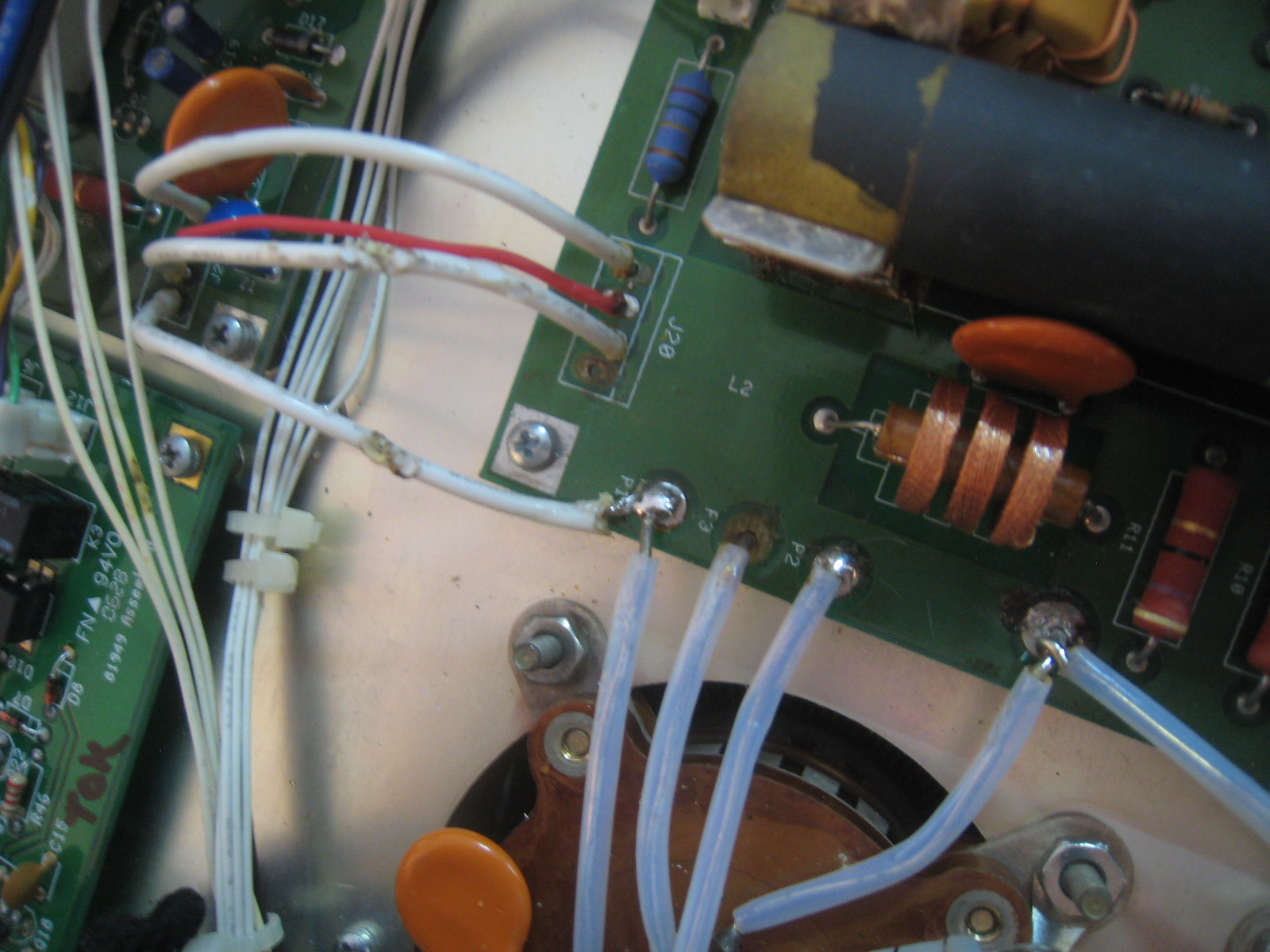
W0CG installed the modified and repaired SWR board. (In September, W9NJY swapped one diode per directions from K6AM.) Discovered also that one of the four wires that we hard-soldered to replace burned yellow connectors to former J20 was loose and not making good contact. Looked at the bottom of that board and the board trace on the bottom was almost totally gone. W0CG moved that wire to connect at P1 on the top of that board. See photo below. Amp is now working and in service at Station 1. Additional parts from K6AM for that SWR board are in box with Titan III additional parts in the Radio Closet.
The bottom of this photo is toward the rear of the amp.
15 December 2013
Tuneup points for 20 meters appeared to have changed and audible arcing on 20 began soon afterward. Arcing was for any power level above about 400 watts.
20 March 2014
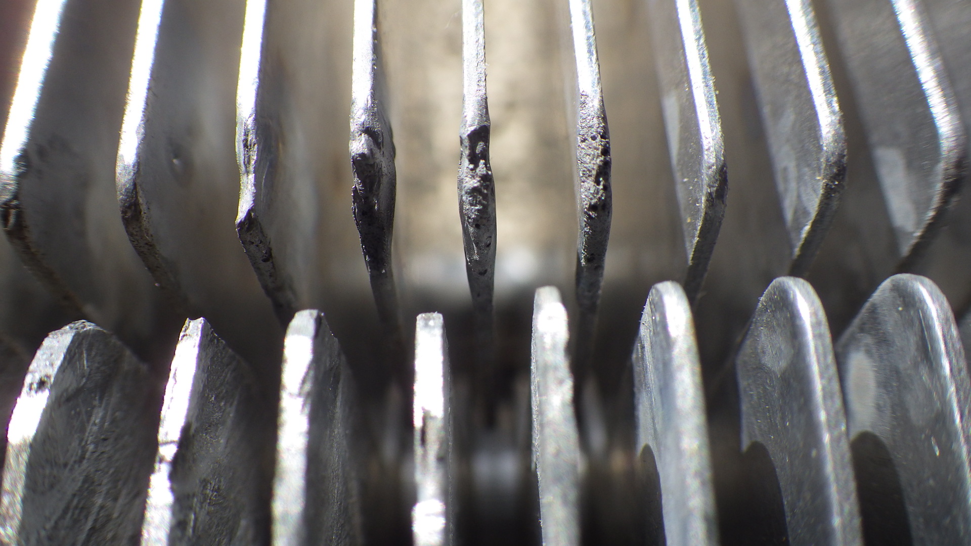
K6AM disassembled amp in early March and determined that the loading cap was arcing on the far side of the case at a point that was inaccessible. Today W0CG removed both the plate and loading variable caps and filed and cleaned all points of arcing and burned material. See photo for before this cleanup. After cleanup and reassembly all functions were good. Tuneup points had all changed so trial tuneups were done on all bands and new tuneup guides taped on front and top of amplifier. Amp easily makes 1500 watts output on nearly all bands. Tuneup is extremely critical and it is very easy to exceed the screen current limit by mistuning the loading capacitor.
23 November 2015
Removed from closet after a year and a half. Opened, inspected, cleaned. Placed in service at Station 1 in CQWW CW. Worked perfectly.
23 November 2017
Only 400 watts output on all bands with 100 watts drive. N7IR and W8WTS spent a full day troubleshootng with no luck. Suspect tube sockets. Placed in closet for further study or possible rebuild by W0CG.
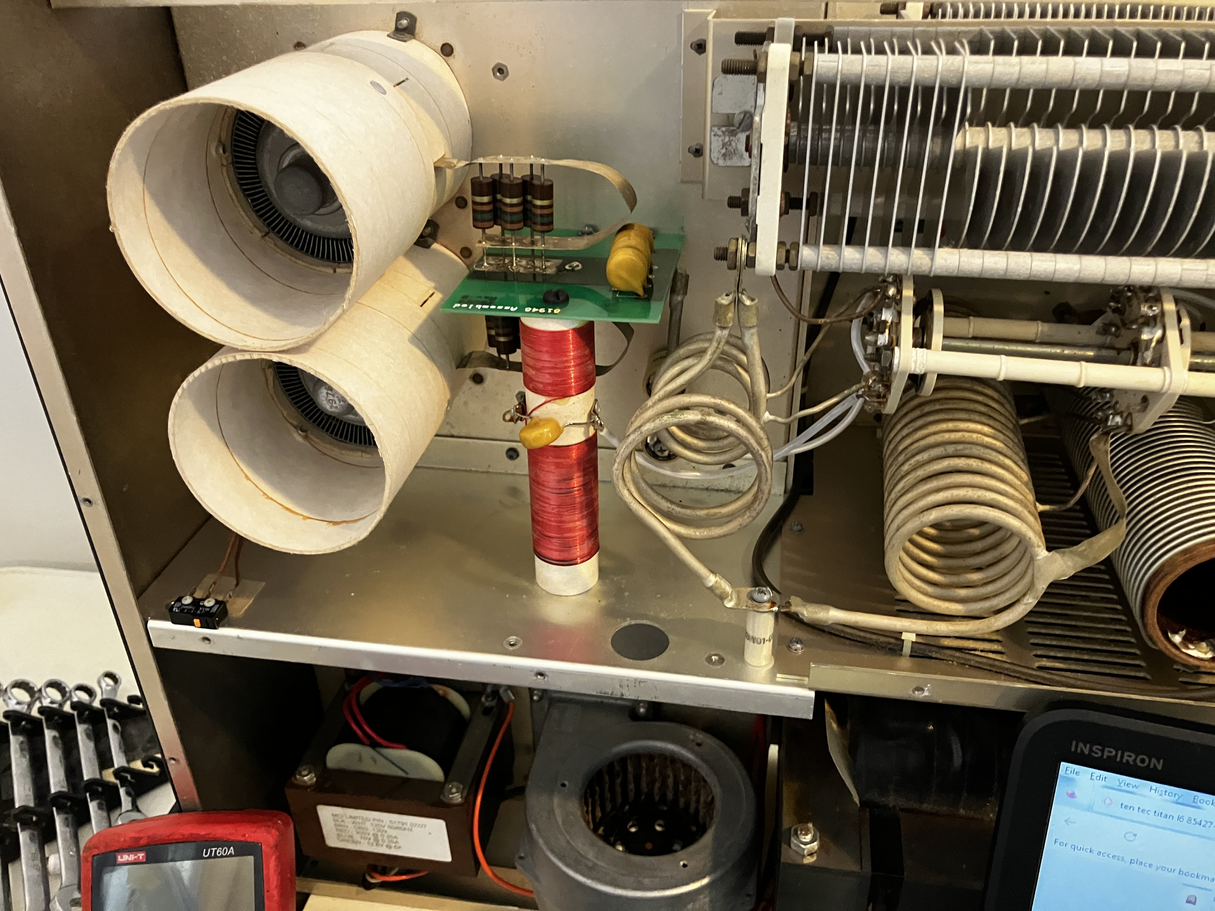
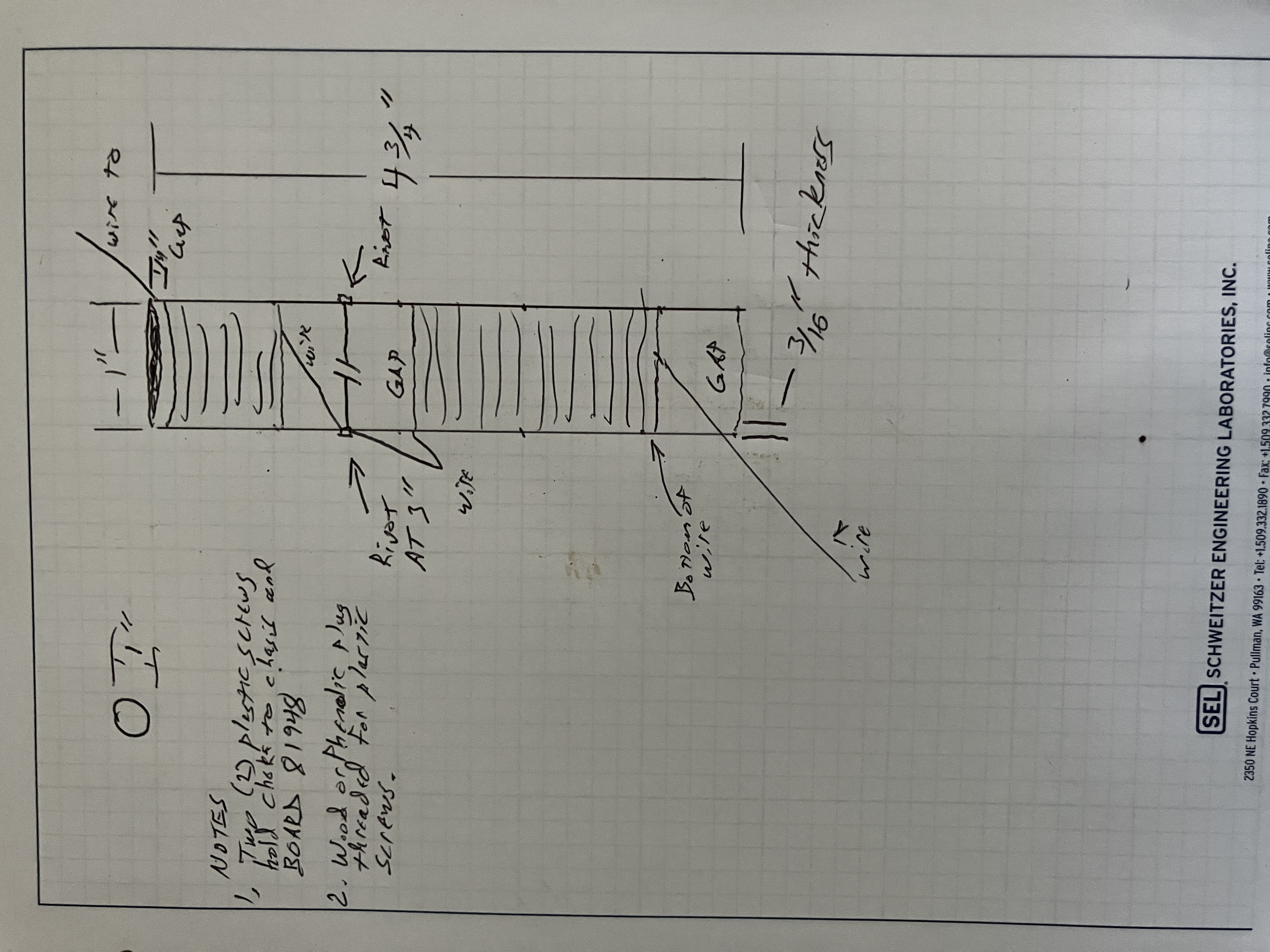
4 March 2026
AC7DC did diagnosis and fond that the plate choke had a broken lead at the bottom near the chassis. He will fabricate a new choke.