Notes on US/JA Two Element Wire Beam
Designed by K6AM 2012. Click here for the design document.
March 2013
Installed temporarily for ARRL DX SSB by hanging the elements off the ends of the US 20 meter yagi. Worked well and after the contest K6AM measured 5.2 DB of gain. W0CG then took the antenna down.
23 - 30 May 2013
Boom fabricated by W0CG in Ohio using parts from DX Engineering and many other sources. Prepped for shipment to Curacao. Click here for the design. Click here for packing list.
16 September 2013
Reinstalled this date on the new W0CG-designed 39.5 foot boom. Used the old wire elements from March 2013 as tuned by K6AM. Feedline connects to the new W9NJY RG-213 coax up the tower and enters shack at top left corner of the new bulkhead.
17 November 2013
Center frequency as tuned was 3.725.
18 November 2013
Added to driven element: 26 inches of wire on back yard leg. Added to reflector: 31 inches of wire on front yard leg. Resonant flat now at 3.525. Marked the correct SSB tuneup points with tape on the wire. And leave the reflector back yard end excess wire wrapped as it is.
19 October 2015
North side of driven element was on the ground when I arrived 2 October. Break was at the feedpoint. Suspect that when the WARC tower guy broke it took down the 80 with it. Repaired today with help from DL8OBQ and IK7YTT.
June 2016
K8ND reported that the south part of the driven element was down. I asked him to roll up the wire and rope and put it safely inside.
16-17 October 2016
K8ND left the wire and rope out and they were stolen. I replaced both sides of the driven element with DX Engineering antenna wire. This is stranded, tough, and much less likely to break. I attached it at the feedpoint such that the coax feed wires and the antenna wires are free to flex, cutting down the change of breaking. I made the new south leg the same length as the CW length of the north leg. Calculated difference in the length of the entire DE between 35.50 and 37.50 is 7.31 ft., and that was exactly the spacing between the pre-existing SSB and CW tape marks I had on the old north leg. I duplicated those lengths exactly in the new north leg, putting the tape marks in the same places. Put antenna up tuned for SSB and got 3840 for resonance with perfect 1:1 SWR. This is about 90 KHz higher than wanted. (Reflector element was tuned for SSB left over from last March and I left it there.)
26 January 2017
Antenna was showing no dips. W8WTS found that the PL-259 on the tower that connects the grey RG-8X to be bad. Will replace with a new one in the daylight tomorrow.
November 2017
Antenna not showing a dip. W0CG found the barrel connector and PL-259 burned black. Replaced connector on RG-8 side. This was a PL-259 with the green plastic core, not Amphenol. Put in new barrel, and cleaned connector on RG-8/X side. Put back in service and worked fine.
January 2018
Problem returned. W8WTS replaced PL-259 on the RG-8/X side and all is perfect.
22 February 2018
W0CG and KB7Q lowered both elements for precautionary maintenance. Cut off the last three feet of rope on both elements and reconnected with fresh rope that was not showing any wear. Took off half the weight from the driven element (one duct seal brick removed) and reassembled.
25 February 2018
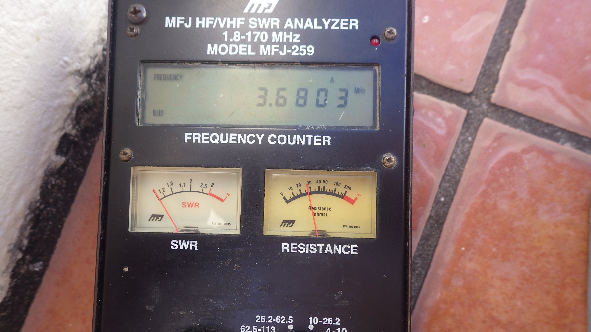
Tuned the antenna per the K6AM procedure below. Attached the tuning coax pigtail to the reflector and re-raised it into position. Driven element was left on the ground. Reflector element was too long, resonant at 3220. Shortened it on the south leg only so as to get resonance at 3440 and taped the wire at the insulator so nobody would be tempted to un-do it. Then tuned the element for 3680, where we got a perfect dip. The old tuning mark was resulting in the reflector being much too long. I put green tape on the foldback point at 10 feet. Properly tuned, exactly 10 ft of wire is folded back and taped into a bundle on the south leg only. See MFJ below, with reflector perfect for SSB.
We have good gain over about 80 kHz (see above). To get full coverage of the contest portions of the band, we will center this window on 3540 for CW and 3780 for phone. This places the resonant frequency of the reflector at 3440 for CW and 3680 for phone. The driven element will be tuned for the center frequencies. We initially tune it for the CW band, then retune for the phone. The exact length the ends are shortened is then marked on the wires with tape and put on a label on the 80 meter antenna switch for future quick mode changes. If the minimum SWR is too high, the impedance of the antenna is too low. It may be raised by placing a coil across the output of the balun at the center of the antenna. Start with 6 turns of #10 solid wire 3” in diameter and 3” long. If you need to adjust the coil, adjust the length and number of turns until the SWR is brought down to 1.2 to 1 or less. This will change the resonant frequency, so re-adjust the lengths of the wires to bring the SWR minimum back to the desired frequency.
27 February 2018
KB7Q and I raised the reflector, then the driven element after much pruning and re-routing of the wires to clear obstacles and trees. The feedline got fouled in 15 beam and had to be disconnected and taken to the ground for routing, then reinstalled. Four trips up the tower for W0CG and about six hours non-stop work. Tuned for SSB using the red foldback mark, which trned out to be still accurate. Antenna tunes perfectly at SSB frequencies. This completes all maintenance and retuning.