Notes on Ridge High Power Remote Coax Switch - W9NJY
May 2013
Need for this proposed by W0CG because the existing RCS-4 switch will not be able to handle 1500 x 3 watts once the triplexer is in service.
June - July 2013
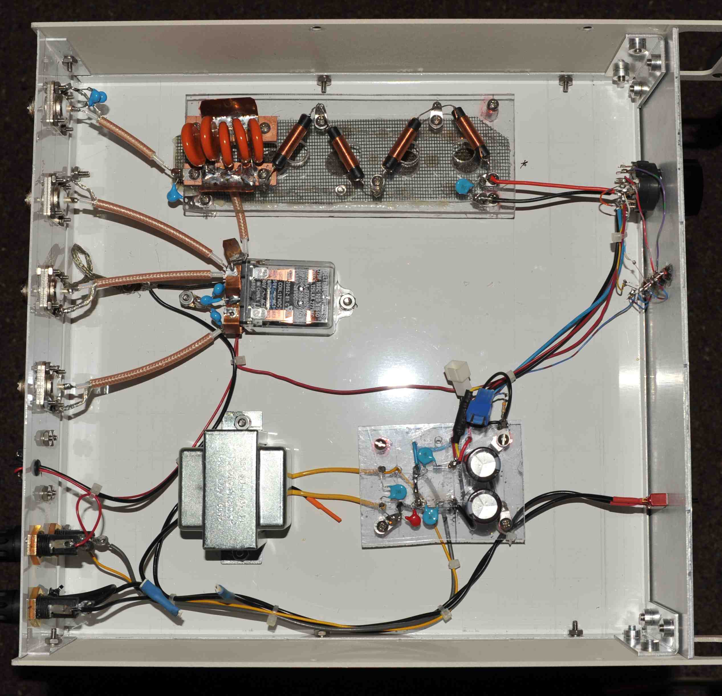
Engineered and built by W9NJY with consultation with N0YY. All costs borne by W9NJY. Click here for schematic. Click here for photo of remote box. Click here for parts list. Click here for photo of shack box.
Finished unit to be tested and then taken to Curacao by W9NJY September 8, 2013.
5 July 2016
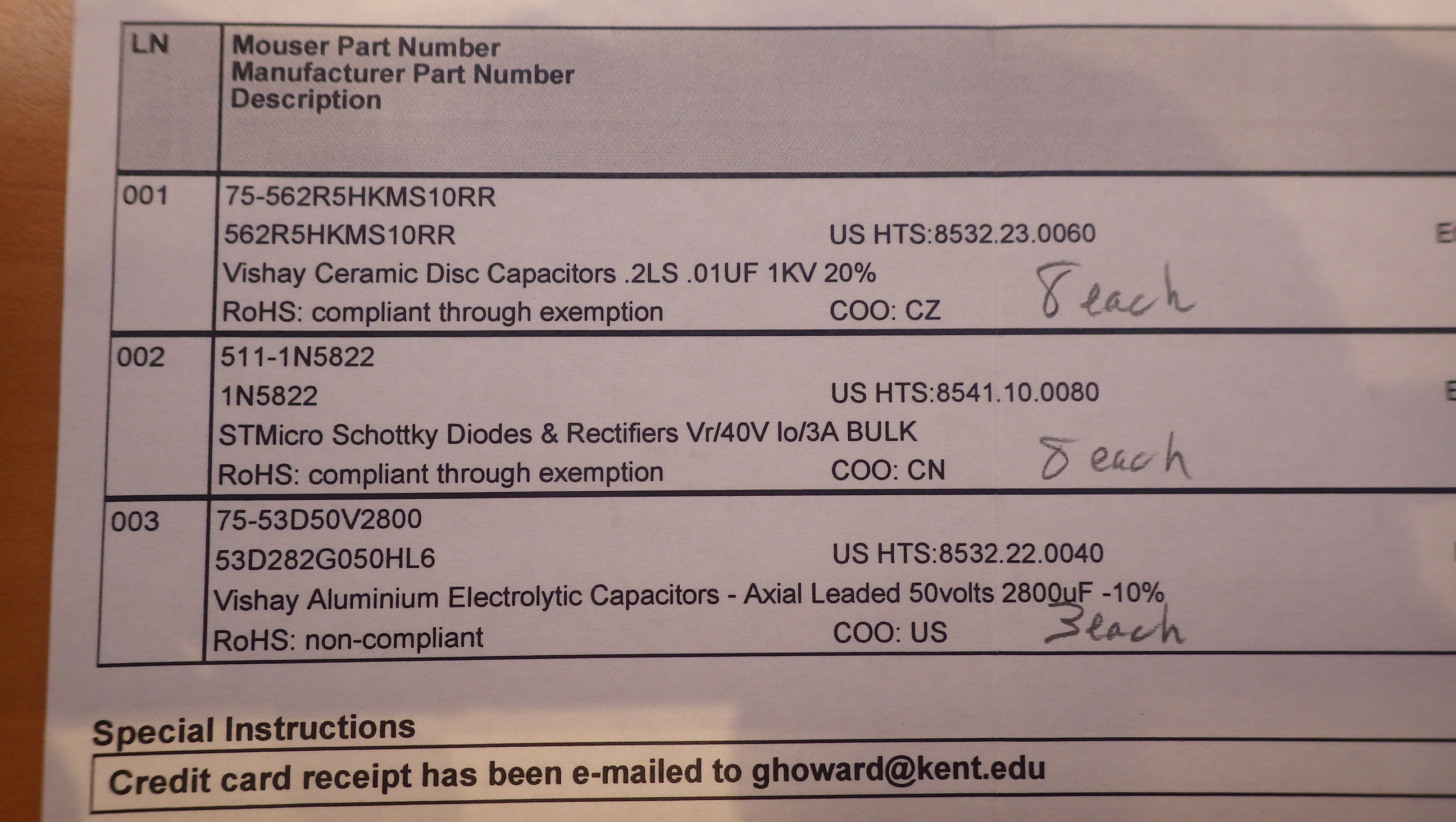
Spare parts ordered for backup. Click here for Mouser invoice of the below spare parts. Click here for Allied Electronics order detail for relays. Power transformer exact replacement bough on EBay 7 July 2016.
* C1... .01 uf 6 KV cap Mouser
75-564R60GAS10, qty 8
* C7... .01 500V disc Mouser DEBF33A103ZA2B, qty 12
* 10 pf 6 KV Mouser 140-602S9-100K-RC; substitute 75-564R60GAQ10, qty 10
* L1... 40 uh 3 A choke Mouser 542-5240-RC, qty 8
* D1... 1N5820 3 amp, qty 4 (Note 1)
* C9... 220 uf 50V electrolytic Mouser 80-ESE228M050AN2AA, qty 4
* T1 12 V 3 a xfmr Radio Shack 273-1511, qty 1
* MOV 1... 17V AC MOV Mouser V27ZA05P, qty 2
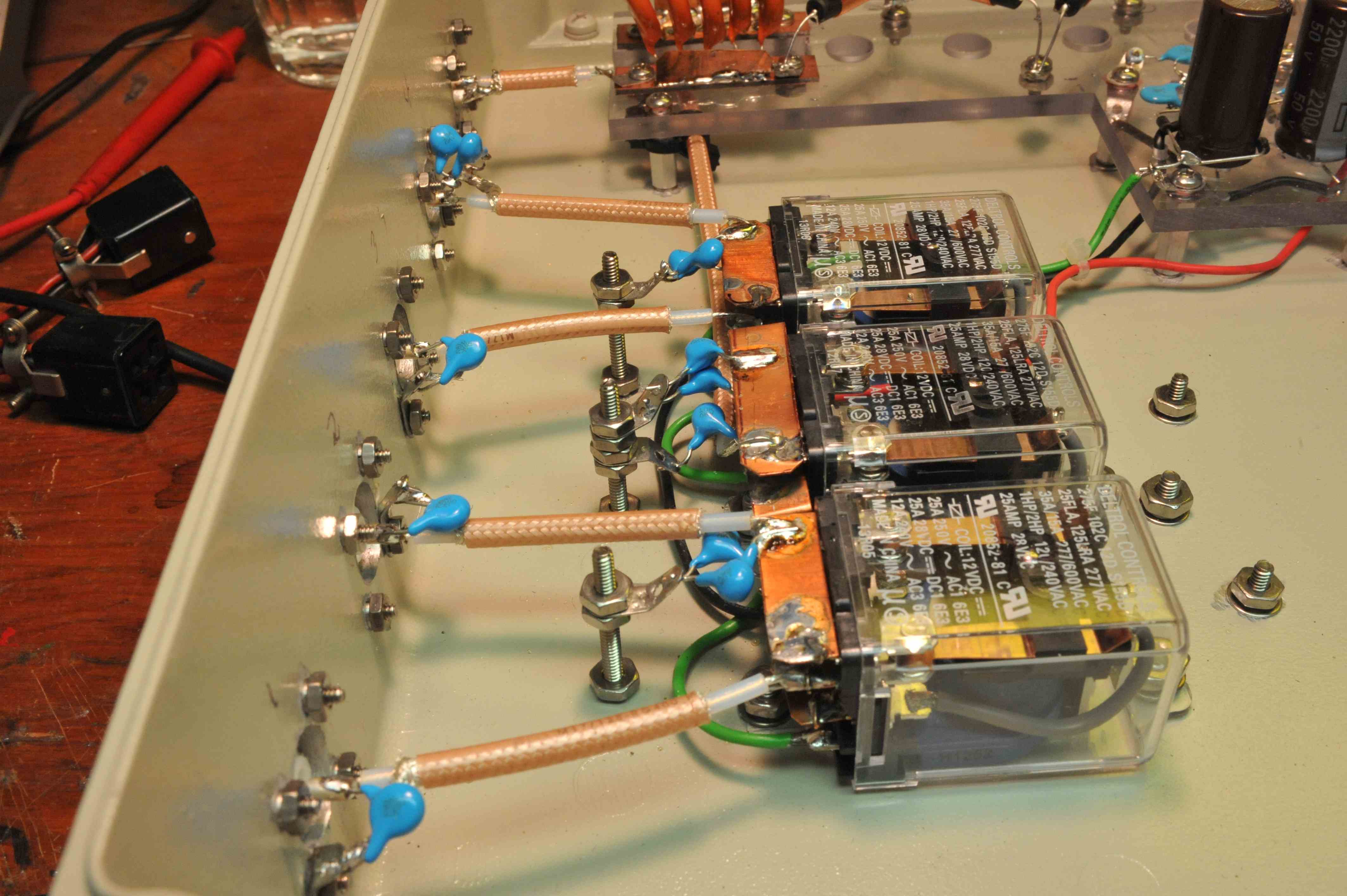
* RLY 1... 10 KW RF relay Deltol Controls 20852-81, Allied Radio, qty 2
* S1 3P4 rotary switch Mouser A30415RNZQ, qty 1
Note 1. Power supply diodes 1N5820 3 amp to replace the present 1N4007 which are
only good for 1 amp.
This kit of spares will be stored inside the switch box in shack.
17 October 2021
Replaced 3 amp fan fuse. W0CG.
20 October 2021
Brought box down from Ridge when certain that the relays were not keying. Replaced one diode, D4 in the negative DC path, sloppily, and the relays came back keying correctly in the shack. Works fine, tests good all ports with full KW in shack.
21 October 2021
Reinstalled on Ridge by W0CG and DL8OBQ. Tests OK.
4 November 2021
While testing the HF-2500 at 2000 watts on 80 meters Ridge the box 3 amp fuse blew and all antennas went dead. Replacement of the fuse resulted in the next fuse blowing in positions 2, 3, 4 when DC was sent up the line. The line showed a 6 ohm short. Brought box down on November 5 but found no failed components inside. Line still showed 6 ohms center to ground. Much troubleshooting found blown black N barrel in the buried joint in the backyard. This is along the inside of the wall, one pilaster north of the US tower guy and a few more inches north. Also found the hardline connector loose and it came off in my hand. Center pin had never been soldered on. Connector was improperly installed.
6 November 2021
Replaced N barrel and double male N adapter in the ditch in backyard. Removed hardline connector and put it on correctly, soldering the center pin and the connector is now on there solidly, installed correctly. Everything works. Shows open cct from shack to Ridge. Replaced Ridge box and tested. All good including 80 meters. Ran tribander and 80 dipole on AA-54 and all curves look OK. SWR on all antennas to the Ridge is much better with the N barrel replaced.
27 December 2021
Ordered parts from Mouser to build a backup DC rectifier board to drive the relays in the Ridge end box.
22 October 2023
K8ND reported 80 meter vee not working. Tested voltages at Ridge and all were correct.
Antenna 4 (Tribander) 0
Antenna 3 (Future) -18.6
Antenna 2 (Future) +18.6
Antenna 1 (80 vee) 13.2 VAC
Dorothy cycled the switch but I heard only one relay click. I tested antennas on
AA-54 analyzer and looked OK. Conclusion is to bring the NJY box back down.
Extensive testing and troubleshooting the next two days showed the left and right relays to be inop, possibly fused by lightning. Installed my backup rectifier board, but had the same exact behavior. Only the middle relay would key (Relay 3) thus connecting the Port 3 antenna. I only have one relay in stock because of cannibalization to use in the NJY box for remote control. W3ACO suggested workaround is to move inv vee to Port 3, and order more relays for future surgery. Tested box with signals in shack, then reinstalled on Ridge.
25 October 2023
Reinstalled box on Ridge with W7MAH, W4IPC, KG5XR. With 80 vee on Port 2, all works perfectly. Need to order 5 Deltrol relays to W8WTS. Relays ordered from "RS" today for delivery to W8WTS.
29 February 2024
Three new relays and four inductors installed by W9NJY. Here are his post-op notes.
Rich and Geoff,
No further autopsy is necessary. Pete K8PGJ and I closely inspected the relays as they came out. Contacts were same as new as viewed through the clear housing. We found that each of the four in-series bias-T 40 uH inductors, which were wound with 26# wire on small linear ferrite rods, had discolored enamel insulation in the middle section of the winding, indicating too much heat was dissipated by each inductor. We then checked the relay coils and found one measured 5 ohms, another measured 10 ohms (one that had failed) and a third had infinitely high resistance (these two failures were relays 2 &3). So in that sense the relays did not fail. And I don’t think that the inductors did either. But there was at least a pulse of too much energy that destroyed two of the three relay coils.
If you look at the attached schematic, it makes sense that the coils in relays 2 & 3 failed together because they are parallel on the distal end of diode D4. Looking at this schematic in the light of day at home and with a cup of coffee in my hand I see that I should have checked electrolytic C21 while I was in there as the pulse that killed the relay coils might have exceeded the 50V rating of C21.
Geoff said he thought that the lightning did this. My guess (and only a guess) is that it was a surge of too much voltage caused by an op hot switching or something like that causing a high standing wave voltage that exceeded the voltage tolerance of the relay coils. My thought is that if it had been a lightning strike there would not have been neat, uniform discolorations of each inductor just in their middle windings. There would have been a more catastrophic picture.
This brings to mind a modification to the remote switch. We know for sure that a lightning strike took out D3 or D4 (Geoff was the surgeon for this replacement operation). Perhaps an MOV or back-to-back Zeners in parallel with C17 would offer a measure of protection if they could handle enough current without a fuse in the circuit.
Another modification I would make were I to build a second remote box would be a vertical panel within the Hammond big box to mount the relays vertically. The tabs would face up and be much easier to access and obviate the need for me to stand on my head to run the copper strap between the tabs.
But that would be a big project right now . . .
73 – Andy
Rich,
Thanks for your comments.
I found the data sheet on the Deltrol Control Relay 20852-81. The coil is rated at 12 VDC and 1.2 W. That comes out to a 100-mA draw. In one switch selection two relays are engaged simultaneously, so the current draw through the inductors would be 0.2 amps max. The Bourns 40 uH inductors are listed as 3-amp devices. Under normal operating conditions, these inductors would never heat up. As I built this in 2013 I was monitoring component temperatures as I went along, although I had only 1 KW of RF available. I did have problems with the bias-T pass caps heating to different temperatures (which I fixed with added copper strap to the PCB strips the caps were soldered to originally) , but there was no inductor heating at all.
I’d suggest that the problem was that either an RF surge or electrical spike with a leading-edge transient that overcame the aggregate 160 uH’s ability to shunt RF. I used calculated values of inductance that I based on two different construction articles (one was Phil Salas of QST) for 1.5 KW switches. They used 28 and 40 uH inductors. So I multiplied by four and mounted the 40 uH Bourns at roughly right angles to each other to prevent mutual coupling.
I brought a 5 KW sensor for an LP-100A wattmeter down to PJ2T in 2013 so we could fully test the control head and remote box with a full-power feed. Three of us on 20-25-10M were able to send 4,250 watts up the line and there was no problem. I presume in CQ WW contests that similar power situations commonly obtain. All of this suggests that the original design parameters were adequate and that the component ratings were fine.
If someone had the Bencher Skyhawk selected rather than the 80M vee and subjected the system to a 1 KW 3.5 MHz signal that was looking at perhaps a 10:1 SWR, the resultant standing wave voltages added to the original RF voltages (I’ll let someone else examine this more accurately with a Smith Chart) could exceed any RF voltage this system could handle. In this instance, increasing the current capacity of the inductors would only allow the relay coils to fail even more assuredly. I’d suggest as an alternative that increasing the inductance beyond its current capacity would allow the rest of the circuit to remain safe. If we were to install MOVs across the relay coils they could reduce the effective resistance and cause even more current to be drawn through the inductors rather than protecting the system. Installing fast-blow 1-amp fuses in series with each MOV/coil might protect everything, but a) I don’t know that any physical fuse would be fast enough and b) we’d still have to fetch the box to install a replacement fuse.
I’d suggest either a lightning strike or mishandled RF could have caused the failure. I doubt the lightning strike of a couple years ago that evaporated the Beverage and destroyed a diode in the remote box would have caused a delayed blowout of relay coils. When was the second strike? Perhaps while no one was around and there was no concomitant damage.
Right now we have a working switching system so I’d leave it alone. If there is another failure, however, Rich, I’d appreciate your input in getting this thing better protected.
Thanks for the discussion!
73 – Andy W9NJY
____________________________________