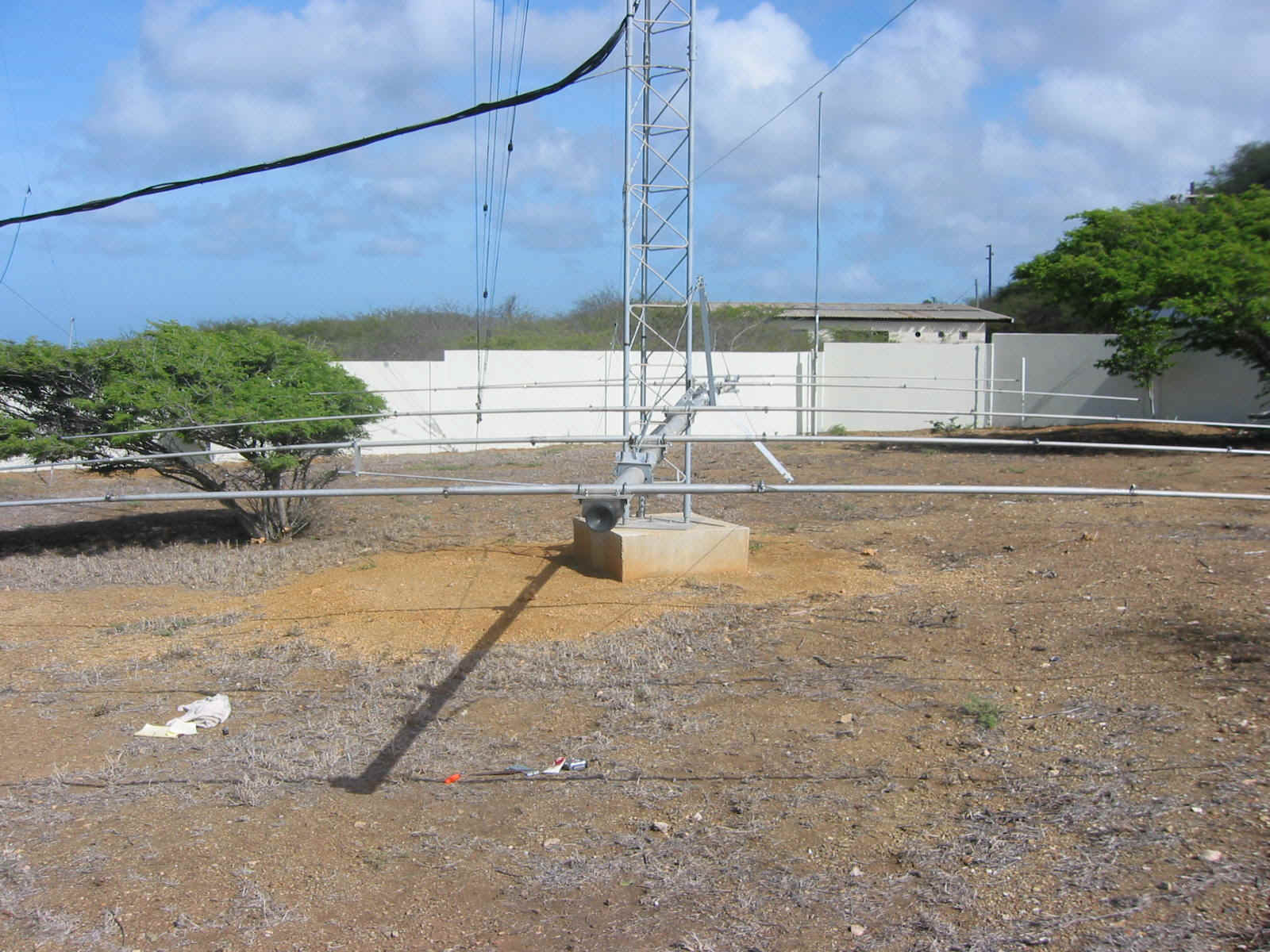
15 Meter US/JA Yagi (Top)
Design Notes

| Caribbean
Contesting Consortium 15 Meter US/JA Yagi (Top) Design Notes |
|
|
Return to Home Page |
Antenna is based on an LTA 3 inch OD 38 foot boom. Pieces were bought from K8DX in April, 2001. Elements are modified from Hy-Gain pieces with swaged tips. Gamma matched.
Built per these dimensions below, as designed by W8AV and WC4E. Truss kit built by W0CG.
| Design run by WC4E 16
Sept 2002 Using YO7.5 Started with 90% of Gain, then tweeked with 60%SWR, 60%of F/R, then 60% of Z. Final tweak a Mix of Gain=30%, F/R=63, SWR=3, Z=4 Element Placements: Feedline: Belden 9913; (12 turns 6" diameter balun = 18.84 ft) + (14.00 ft along boom to DE) + (15 ft minimum up and down tower from stack box) = 47.84 ft. 1/2 wave at 21.200 MHz = 23.21 ft * Vf of .84 = 19.49 ft. Three half waves = 58.48 ft. Therefore, each feedline is made from 3/2 wave lengths 58 ft 6 in of Belden 9913.
Other Photos: | Boom Pieces | Element Tips on D1 | Almost Finished | Truss Detail | W0CG Fabricating Balun for this Antenna, 8 Oct 2002, in Ohio | Installation: 20-21 November 2002 | Up on the Tower |
|
As Built by W0CG, 11-18 Sept 2002 |
Above was modeled using this YO file.
W8AV/WC4E 15 Meter 5 Element
21.000 21.225 21.450 MHz
5 elements, inches
1.2500 1.0625 0.8750 0.8125 0.6250 0.5000
0.0000 13.0000 5.0000 36.0000 5.0000 29.0000 56.0737
55.7007 13.0000 5.0000 36.0000 5.0000 29.0000 49.0140
121.4194 13.0000 5.0000 36.0000 5.0000 29.0000 47.3769
266.1793 13.0000 5.0000 36.0000 5.0000 29.0000 42.6732
446.0000 13.0000 5.0000 36.0000 5.0000 29.0000 35.6186
Bracket: 0 4.0000 6.5000 0.0000 0.2500
Modeling shows that we need a big vertical lobe at 11 degrees of elevation. This translates to a height of 60 to 55 feet. Nothing is gained for US by going higher. Point it at 343 degrees magnetic to catch East end West coast with center on JA. Fits the 3 dB beamwidth needed perfectly.
Geoff,
I started from scratch again this monring and let the computer chug on the antenna for about 4 hours. Here is a revised set of dimensions for the USA 15 meter antenna
Locations:
R 2"
DE 74.092" (74 3/32")
D1 123.946" (123 15/16")
D2 264.233" (264 7/32")
D3 442"
Lengths:
1 1/4" tubing 18" (including swage)
7/8" tubing 40" (including swage)
5/8" tubing 29" (includiung swage)
1/2" tubing
R 55.704" (55 11/16")
DE 46.500" (46 1/2 ")
D1 46.032" (46 1/32")
D2 39.448" (39 7/16")
D3 27.614" (27 5/8")
Antenna Gain 10.02 dB @ 21.225 MHZ
F/B 26.19 dB
VSWR
21.000 MHz 1.62
21.225 MHz 1.09
21.450 MHz 2.68
That is about the best I can do on VSWR with this boom length. Don't know why the model predicted different results for the previous run. Maybe a funky bit got set somewhere. That has happened to me once before when I was running the program come to think of it.
Lemme know what you think.
73....de Goose W8AV
.* Pretty please make notes on
where you got things from so that they can go back in the same places. That will save us
on the CQWW CW team a LOT of time looking for stuff.
* You'll have to lower down the top 10 yagi and take the 75 inv vee and possibly one of
the PJ9JT tower guys loose temporarily to get the needed clearance.
* Run the guy wire tram line down to the ground out where we raised the 20 from last
October. Guy wire is on a coil on the east porch and deadends are on the shelf right over
the door going into the utillity room. I suspect it will work best to tram the antenna to
a point about 20 feet below the final position for the 15 yagi and then rope it straight
up from there.
* Run the yellow pull rope to the tram pulley through another pulley on the tower, sightly
below the tram line attachment point. Pulleys are on the floor in the radio closet along
the rear baseboard and the yellow rope is on the back shelf in the utility room. You'll
need to use the ladder to get it down.
* Prepare the antenna by disconnecting one of the lateral Phillystran trusses that blocks
the antenna from butting up to the tower. Tape it REALLY well to the boom so you can
reconnect it after the antenna is in place.
* Use the nylon straps hanging on the bar in the radio closet to attach to the boom and to
make a place to hang the antenna from the tram pulley. Tape them to the boom so they won't
slide inward under load.
* Put the feedline/balun assembly that I'll ship to you on the boom with Scotch 33 and tie
wraps. Make it really stout.
* Use a bit of conductive grease on the coax threads on the beam before hooking up the
connector. It is in a small white syringe-tube in the box on the floor of the radio closet
that has WD-40, duct seal, 3 in one oil, etc. Then lightly plier-tighten the PL-259, wrap
it in a tight and thick layer of duct seal (grey, on floor of radio closet), and wrap the
duct seal with Scotch 33. Coat the tape with Scotchkote (in radio closet on floor).
* Fasten the steel tram guy to the car rear axle. There are two comealongs in the utility
room on the shelf over the entrance door. Tension it moderately tight, but don't damage a
tower leg.... :)
* Get your whole crew to help you move the antenna over the wall and out into position --
you will NOT be able to put it on the ground because of the lateral truss braces -- hang
it on the tram line right away. You may have to loosen the director of the 80 loop to get
clearance to the wall.
* Use light yellow ropes (orange coils on shelf in the utility room) for tag lines on the
boom and also be sure to put a tag line on the pulley to pull it back DOWN the tram --
gravity sometimes does not do the job)
* Hook up the MFJ meter (you will have to bring one) and tram the antenna about 30 feet
up. Adjust the driven element length to get a dip at 21.150, then start adjusting the
gamma match capacitor rod and the position of the shorting bar to get the SWR as low as
possible so you see 50 + j0 or as close as possible at the feedpoint. I have several of
these K3LR gamma matched ants at home and they will match almost perfectly. It just takes
a LOT of time and patience. You will have to tram up and down a bazillion times until it
tunes right. The gamma rod came from a functioning K3LR 15 yagi almost exactly like this
one so take heart, you KNOW it will tune.
* Once you are satisfied with the tuning, tighten the 10-32 bolts (two of them) in the
gamma bar SERIOUSLY tightly (I will send you stainless versions of these) and then put a
double nut on both bolts. These have a terrible tendency to come loose on these antennas
and cause future problems. Then spray paint the bolts and nuts a couple times with grey
enamel from the floor in the other west bedrom closet
* Raise the antenna into position. If his leg is better, then "Beast Bolia, the Human
Winch" can do so from the base of the 80 foot tower. You want it about 8 feet below
the 20 yagi we put up last year. Bolt it to the tower using one of the stainless U bolts I
will ship to you soon. Be really careful -- too tight here can crimp a tower leg.
* Have someone check the SWR, loading, and center point from the shack, and then hit the
antenna with full power RF for awhile (make some Qs) to be sure before you final install
it. If necessary, tweak the length of the driven element -- this will probably be
necesssary once the antenna is in position close to the 20 yagi above. Take your time and
get it right like we did on the 20 last year -- that extra effort will pay off on the air
because the amps will be happy with the load and will couple more power into the antenna.
* Once it loads OK, add three more U bolts to the tower leg and tighten not too tightly.
With four U bolts, none of them have to be super tight.
* Carefully untape the one Phillystran lateral from the boom and connect it around the
tower and into the aluminum lateral bracket
* Use the turnbuckles at the top of the steel truss post to bring the ends of the boom up
parallel with the ground and then about an inch higher than that, then double-check that
the top truss hardware is all tight. Wire in a piece of safety wire so that these
turnbuckles can't move on their own. Blue insulated #12 Cu wire makes good safety wire.
* Use the bolts on the ends of the lateral aluminum brackets to pull all four Phillystran
lateral boom guys moderately tight and to straighten the boom, then cinch all that
hardware tight. This keeps the boom from flopping around in the wind gusts.
* Connect the coax to one of the open ports on the 15 stackbox. Be sure somebody is
monitoring in the shack so you get it on the port labeled "Top 15" -- NOT
"Bottom 15." Use the same combo of conductive grease, duct seal, tape, and
Scotchkote as you did at the feedpoint.
* Un-tension the tram come-along
* Reinstall the 10 yagi and any wires and guys you took loose
* VERY IMPORTANT: Install two boom "wind trusses." These will be identical to
the ones above you on the 20 yagi -- they run from the boom down to the ocean guy. (I left
the boom brackets loose until you have the trusses installed.) These are ABSOLUTELY
CRITICAL to prevent the tower from over-twisting in the rugged windy environment by the
ocean. The roll of Phillystran is on the floor in the other closet in the west bedroom. I
will send you the six clips you'll need to make these truss pieces. There should be enough
Phillystran. Make one complete run to the ground from the boom first, (run it from the
boom to the ocean guy), and ONLY THEN cut the piece. This stuff is very expensive and we
can't waste any. If there is not enough left to do the second boom guy, use yellow rope or
whatever you can grab -- there has GOT to be a pair of these installed. You will see that
I left the ground parts of these pre-installed on the ground at the ocean guy -- all you
have to do is untape them, and hook them up, following the example of the 20 yagi.
* Wrap some tape or something around the turnbuckles on the ground at the ocean guy to
keep them from corroding like the ones for the 20 wind trusses already have. The
galvanizing is useless against the salt spray.
* Clean up and stow all ropes, tools, and suffnjunk.
Have fun with this antenna -- I predict that at the 55-60 foot height it will be a killer
into the US. The model says so, too!
We'll add a bottom 15 antenna later. It won't be identical, so it won't be a true stack,
but it will still be very useful.
(You might want to lower the bottom 10 about 6 feet lower if there is enough coax to do so
-- the 10 yagis are too close together to work well as a stack -- they should be about 33
feet apart. You can can't the bottom one more toward the East US if you want like you did
last year.)