Antenna Design Notes
| Caribbean
Contesting Consortium Antenna Design Notes |
|
|
Return to Home Page |
Design Approach
Our approach to designing the antenna system at PJ2T is as follows.
1. Define all foreseen operating scenarios (table below.) Please send your added scenario suggestions to W0CG or W8AV -- this is all in draft!
2. Obtain data tables analyzing preferred vertical radiation angles for the antennas. These are based on the statistical analysis of Dean Straw (N6BV) of the ARRL. These tables show the range of radiation angles that we will attempt to design our antennas to cover.
3. Place antennas on towers and azimuths that will maximize coverage of the needed elevation angles and azimuths. These designs are particularly challenging because the QTH is on the "wrong" side of the island for salt water shots to Europe, and because we must deal with difficult terrain toward Europe and poor ground conductivity everywhere except for south shots.
4. Cross-reference each operating scenario to various antenna selections.
Scenarios
| Scenario | Contest | Category | Band | Situation | Solution |
| 1 | CQWW, WPX | Multi-Single, Single Op | 20 | Evening, 0000 - 0300, run Eu/US/JA
|
Feed 20 yagi on Eur at 100 ft and 20 fixed US at
80 ft Use tribander (A-3WS) fixed on SA at 50 feet for occasional QSOs south |
| 2 | CQWW, WPX | Multi-Single, Single Op | 15 | Evening, 0000 - 0300, run Eu/US/JA | Feed 15 fixed Eur at 90 ft and 15 fixed US at 70
ft Use tribander (A-3WS) fixed on SA at 50 feet for occasional QSOs south |
| 3 | CQWW, WPX | Multi-Single, Single Op | All | Mult pick on all bands | Use unused ants; for 20, 15, 10 mults use CL-33 at 85 feet, rotatable. |
| 4 | CQWW, WPX | Multi-Single, Single Op | 10 | Evening, 0000 - 0300, run US/JA | Use 10 yagi at 60 feet fixed US/JA Use tribander (A-3WS) fixed on SA at 50 feet for occasional QSOs south |
| 5 | CQWW, WPX | Multi-Single, Single Op | 20 | Night 0300 - 1000, run Eu/US/JA | Feed 20 yagi on Eur at 100 ft and 20 fixed US at
80 ft Use tribander (A-3WS) fixed on SA at 50 feet for occasional QSOs south |
| 6 | CQWW, WPX | Multi Single, Single Op | 40 | Evening, night, run Eu/US/JA | Use 40 yagi at 107 feet, with compromise heading
of 005 degrees Use tribander (A-3WS) fixed on SA at 50 feet for occasional QSOs south |
| 7 | CQWW, WPX | Multi Single, Single Op | 80 | Night, run US and some Eur | Use W8AV steerable wire vertical array and mix receive signals from US and Eur beverages |
| 8 | CQWW, WPX | Multi-Single, Single Op | 160 | Night, run US and some Eur | Use inverted L and mainly US beverage |
| 9 | CQWW, WPX | Multi Single, Single Op | 20 | Night, look for VK/ZL opening about 0900 | Use 20 at 100 feet, rotated west |
| 10 | CQWW,WPX | Multi-Single, Single Op | 10 | Morning 1000 - 1500, run Eur | Use 10 yagi at 80 feet, fixed Eur Consider CL-33 at 54 feet for long path band-opener. Use tribander (A-3WS) fixed on SA at 50 feet for occasional QSOs south |
| 11 | CQWW, WPX | Multi-Single, Single Op | 15 | Morning 1100 - 1500, run Eur | Use 15 yagi at 90 feet, fixed Eur Consider CL-33 at 54 feet for long path band-opener.. Use tribander (A-3WS) fixed on SA at 50 feet for occasional QSOs south |
| 12 | CQWW, WPX | Multi-Single, Single Op | 20 | Morning 1200 - 1400, run Eur, US | Feed 20 yagi on Eur at 100 ft and 20 fixed US at
80 ft Use tribander (A-3WS) fixed on SA at 50 feet for occasional QSOs south |
| 13 | CQWW, WPX | Multi-Single, Single Op | 10 | Afternoon 1600 - 2000, run US and some Eur | Use 10 yagi at 80 feet fixed Eur and 10 yagi
stack at at 60/35 feet fixed US, fed together Use tribander (A-3WS) fixed on SA at 50 feet for occasional QSOs south |
| 14 | CQWW, WPX | Multi-Single, Single Op | 15 | Afternoon 1600 - 2100, run US and some Eur | Use 15 yagi at 90 feet fixed Eur and 15 yagi
stack at 70/45 feet fixed US, fed together Use tribander (A-3WS) fixed on SA at 50 feet for occasional QSOs south |
| 15 | CQWW, WPX | Multi-Single, Single Op | 20 | Afternoon 2100 - 2359, run US and some Eur, some JA | Use 20 yagi at 100 feet on Eur, 20 yagi at 80 feet fixed US/JA |
| 16 | CQWW, WPX | Multi-Single, Single Op | 10 | Afternoon 2100-2359, run US and some JA | Use 15 stack at 70/45 feet, fixed US/JA |
| 17 | ARRL | Multi-Single, Single Op | 20 | Run | Use 20 yagi at 80 ft |
| 18 | ARRL | Multi-Single, Single Op | 15 | Run | Use 15 yagi stack at 70/45 ft |
| 19 | ARRL | Multi-Single, Single Op | 10 | Run | Use 10 yagi stack at 60/35 ft |
| 20 | ARRL | Multi-Single, Single Op | 40 | Run | Use yagi at 107 ft |
| 21 | ARRL | Multi-Single, Single Op | 80 | Run | Use 80 vertical wire array, with northwest selected |
| 22 | ARRL | Multi-Single, Single Op | 160 | Run | Use inverted L and US beverage |
| 23 | All contests | Multi-Multi | All | Run | Operator for each band selects the combination of antennas most suitable to conditions. |
Design Targets -- Preferred Vertical Radiation Angles
(The data used here are from the ARRL web site, "Enhanced Elevation-Statistical Files for YT." )
A. Caribbean to USA
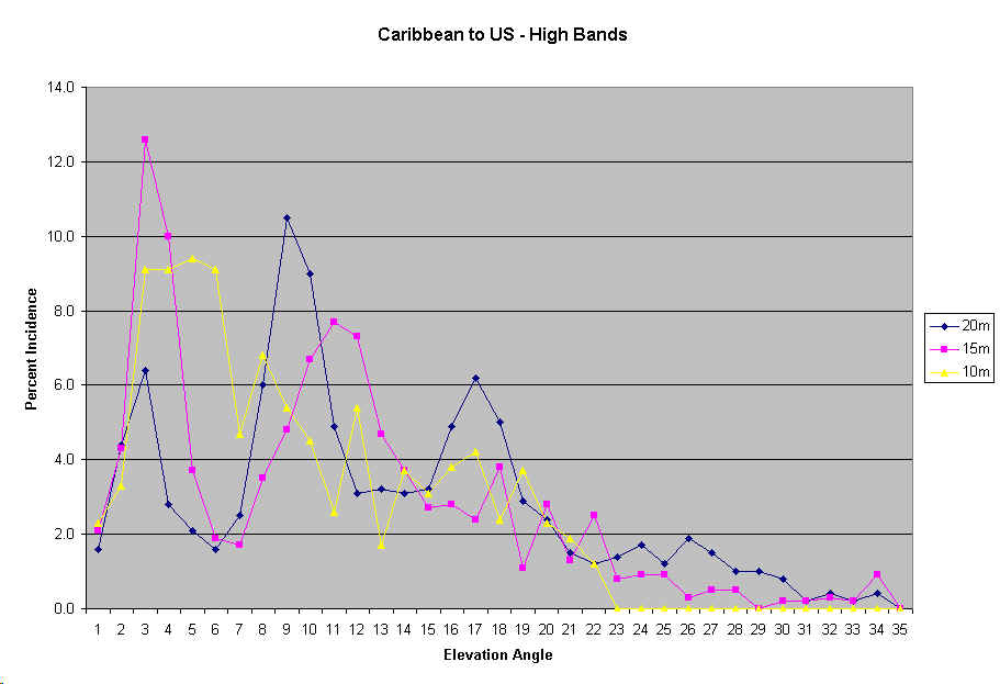
It is a myth that radiation angles to the States from the Caribbean are all high angle. In fact, most paths are one-hop, low angle paths. Team Vertical proved this at 6Y5A and in many other operations. See their design information at http://www.k2kw.com/verticals/whyvert.html . The following table verifies that high angles are of no importance in working the States from the Caribbean. See, for example, the 20 meter column. This is telling us that paths from Panama (close to our latitude) to the US on 20 are at an angle of 9 degrees 10.5% of the time, and an angle of 10 degrees 9% of the time. High angles (above 20 degrees) are of very little importance on 20 to the States. This means that our US yagi may need to be higher than conventional wisdom might dictate.
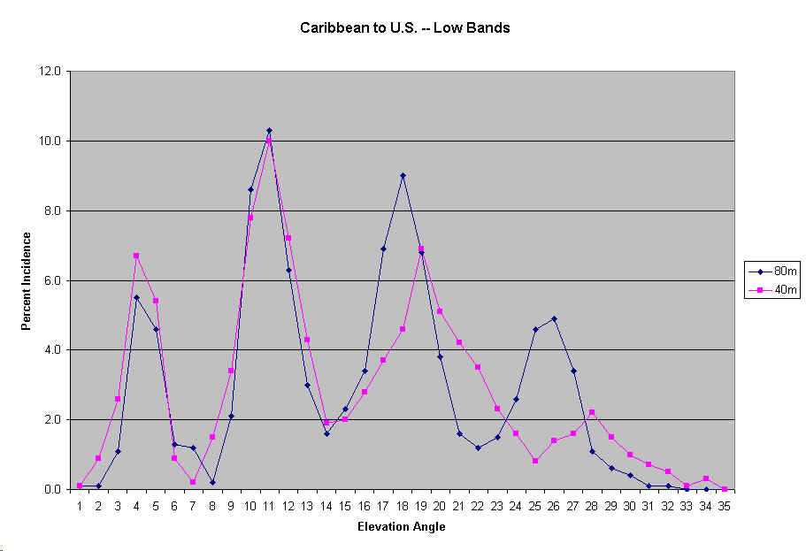
Panama to USA
Elev      80m    40m    30m    20m    17m    15m    12m    10m
 1        0.1    0.1    0.6    1.6    2.0    2.1    0.6    2.3
 2        0.1    0.9    1.9    4.4    6.6    4.3    3.0    3.3
 3        1.1    2.6    3.1    6.4   10.3   12.6    9.8    9.1
 4        5.5    6.7    4.1    2.8    6.2   10.0   13.0    9.1
 5        4.6    5.4    6.5    2.1    2.7    3.7    9.0    9.4
 6        1.3    0.9    3.5    1.6    1.4    1.9    3.6    9.1
 7        1.2    0.2    1.7    2.5    1.7    1.7    3.0    4.7
 8        0.2    1.5    3.7    6.0    4.0    3.5    4.1    6.8
 9        2.1    3.4    6.4   10.5    8.9    4.8    4.7    5.4
10        8.6    7.8    5.3    9.0   10.0    6.7    6.2    4.5
11       10.3   10.0    6.8    4.9    8.1    7.7    3.9    2.6
12        6.3    7.2    5.5    3.1    3.6    7.3    3.9    5.4
13        3.0    4.3    4.6    3.2    3.4    4.7    4.3    1.7
14        1.6    1.9    4.8    3.1    2.0    3.7    5.6    3.7
15        2.3    2.0    4.5    3.2    1.9    2.7    4.8    3.1
16        3.4    2.8    5.1    4.9    4.3    2.8    3.5    3.8
17        6.9    3.7    5.2    6.2    2.7    2.4    3.9    4.2
18        9.0    4.6    3.9    5.0    4.6    3.8    3.6    2.4
19        6.8    6.9    1.8    2.9    2.5    1.1    1.5    3.7
20        3.8    5.1    2.4    2.4    3.0    2.8    2.1    2.3
21        1.6    4.2    2.6    1.5    1.7    1.3    0.9    1.9
22        1.2    3.5    3.1    1.2    1.5    2.5    1.8    1.2
23        1.5    2.3    3.3    1.4    0.4    0.8    0.0    0.0
24        2.6    1.6    2.8    1.7    0.7    0.9    0.8    0.0
25        4.6    0.8    1.5    1.2    0.5    0.9    0.5    0.0
26        4.9    1.4    0.9    1.9    0.7    0.3    0.9    0.0
27        3.4    1.6    0.4    1.5    0.4    0.5    0.7    0.0
28        1.1    2.2    0.9    1.0    0.6    0.5    0.5    0.0
29        0.6    1.5    0.3    1.0    0.2    0.0    0.0    0.0
30        0.4    1.0    1.0    0.8    1.1    0.2    0.0    0.0
31        0.1    0.7    0.7    0.2    0.1    0.2    0.0    0.0
32        0.1    0.5    0.3    0.4    0.8    0.3    0.0    0.0
33        0.0    0.1    0.2    0.2    0.1    0.2    0.0    0.0
34        0.0    0.3    0.6    0.4    1.0    0.9    0.0    0.0
35        0.0    0.0    0.2    0.0    0.4    0.0    0.0    0.0
This data is best-visualized as a graph. The WARC band data has been removed, and only high band (20, 15, 10) data is shown here.
This graph clearly shows the angles required for good coverage to the US on the high bands, and serves as the design target for our arrays for 20, 15, 10 for U.S. coverage.
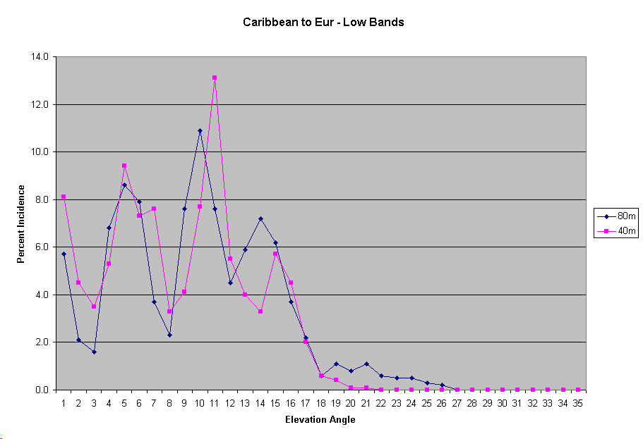
Similarly, here is the graph for 80 and 160.
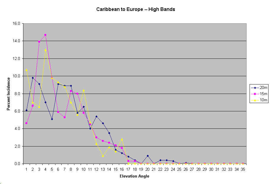
B. Caribbean to Europe
Here are the data and graphs that constitute our design targets for the Europe antennas.
Panama to Europe
Elev      80m    40m    30m    20m    17m    15m    12m    10m
 1        5.7    8.1    3.4    6.1    3.9    4.6    8.1   10.7
 2        2.1    4.5    9.8    9.8   12.9    6.6    5.0    7.0
 3        1.6    3.5    7.5    9.1   18.1   13.9   10.6    6.5
 4        6.8    5.3    5.4    7.0   10.7   14.7   11.8   13.0
 5        8.6    9.4    9.2    5.1    7.2    9.8    9.8    9.8
 6        7.9    7.3    9.5    9.1    5.7    5.9   11.1    9.3
 7        3.7    7.6    6.7    8.9    7.7    5.3    5.8    8.8
 8        2.3    3.3    6.5    8.9    8.5    8.3    7.1    7.0
 9        7.6    4.1    5.9    5.8    7.2    8.0    7.8    5.6
10       10.9    7.7    4.6    6.5    2.7    5.8    6.3    8.4
11        7.6   13.1    6.3    4.0    4.9    4.5    4.0    4.7
12        4.5    5.5    6.5    5.4    3.7    3.0    3.0    2.3
13        5.9    4.0    5.3    4.6    2.6    2.6    1.8    0.9
14        7.2    3.3    3.1    3.5    2.4    2.4    3.3    1.9
15        6.2    5.7    1.9    1.6    0.9    2.1    1.8    1.4
16        3.7    4.5    2.6    1.2    0.1    1.8    1.0    2.8
17        2.2    2.0    2.1    0.8    0.3    0.3    0.3    0.0
18        0.6    0.6    2.2    0.4    0.4    0.3    0.5    0.0
19        1.1    0.4    0.7    0.0    0.0    0.0    0.3    0.0
20        0.8    0.1    0.4    0.9    0.1    0.0    0.5    0.0
21        1.1    0.1    0.5    0.0    0.0    0.0    0.3    0.0
22        0.6    0.0    0.0    0.4    0.0    0.0    0.0    0.0
23        0.5    0.0    0.0    0.4    0.0    0.0    0.0    0.0
24        0.5    0.0    0.0    0.3    0.0    0.0    0.0    0.0
25        0.3    0.0    0.0    0.0    0.0    0.0    0.0    0.0
26        0.2    0.0    0.0    0.1    0.0    0.0    0.0    0.0
27        0.0    0.0    0.0    0.0    0.0    0.0    0.0    0.0
28        0.0    0.0    0.0    0.0    0.0    0.0    0.0    0.0
29        0.0    0.0    0.0    0.0    0.0    0.0    0.0    0.0
30        0.0    0.0    0.0    0.0    0.0    0.0    0.0    0.0
31        0.0    0.0    0.0    0.0    0.0    0.0    0.0    0.0
32        0.0    0.0    0.0    0.0    0.0    0.0    0.0    0.0
33        0.0    0.0    0.0    0.0    0.0    0.0    0.0    0.0
34        0.0    0.0    0.0    0.0    0.0    0.0    0.0    0.0
35        0.0    0.0    0.0    0.0    0.0    0.0    0.0    0.0
The above elevation angles constitute the design targets for the low band antennas. The astonishing point is that any radiation above 18 degrees elevation is wasted.
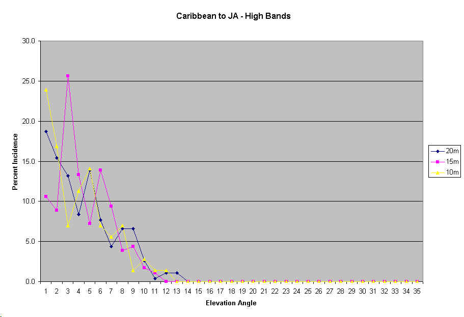
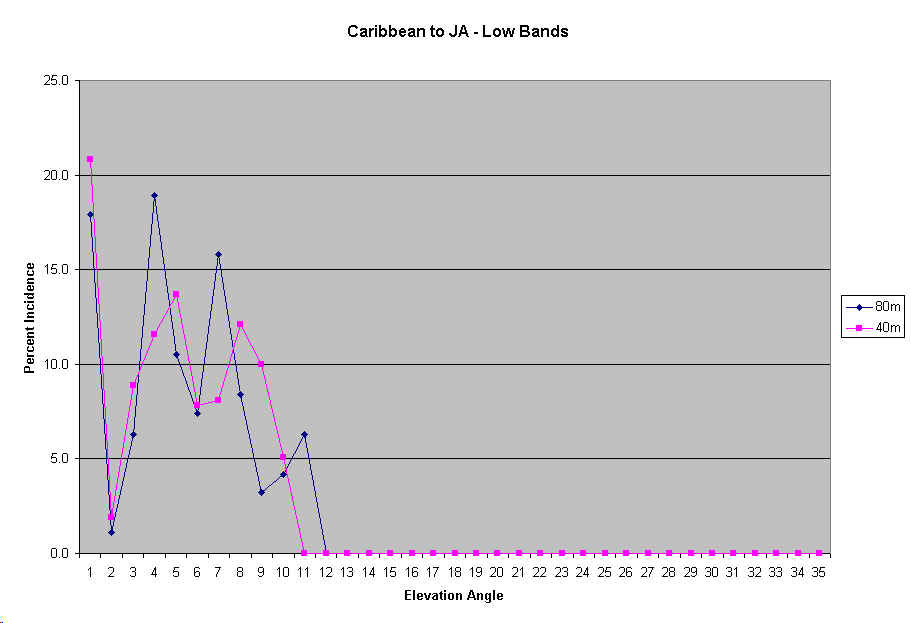
C. Caribbean to Japan
Designs
A. 20 Meters to Europe
This is the worst of all our situations. Studies with K6STI's TA, factoring in the effect of the cliff, show that domination on 20 into Europe will be nearly impossible. (Sorry, I can't extract the graphs from the TA program and show them here.) Even at a height of 100 feet, radiation below 20 degrees comprises only a small proportion of the vertical pattern. However, placing the Europe Yagi at 100 feet as opposed to the present 54 feet results in almost 6 dB more signal at an angle of 5 degrees than the existing 54 foot high antenna. Stacking provides no advantage whatsoever because it still fails to fill in any of the missing low angles, and all needed high angles are well-covered by the one antenna. The ideal design would be an antenna on the ridge, but a yagi would have to be at 100 feet to be effective. It would be a good future experiment to place a pair of verticals with many radials on the ridge. Best Design: 5 el at 100 ft, rotatable to cover Africa also.
B. 15 Meters to Europe
On the Europe path, the effect of the cliff dominates. Higher is better, providing better coverage the higher we go into the important angles of 2 to 6 degrees. There are no serious coverage gaps with an antenna at 90 feet, and any angles above 18 degrees are worthless. Stacking provides no advantage whatsoever because it still fails to fill in any of the missing low angles.An antenna on the ridge is not dramatically better unless it is at least 75 feet high. A good future experiment would be phased verticals for 15 over many radials on the ridge. Best Design: The highest possible (this will be 90 feet) monoband yagi, fixed on Europe.
C. 10 Meters to Europe
Same guidelines as for 15 meters to Europe. The higher the better, but the highest possible will be 80 feet, to maintain reasonable spacing from the 15 yagi above. A 10 yagi only 40 feet high on the ridge would preform better than the one at 80 behind the ridge. Stacking provides no advantage whatsoever because it still fails to fill in any of the missing low angles.Best Design: The highest possible (this will be 80 feet) monoband yagi, fixed on Europe.
D. 20 Meters to US
TA shows that an antenna height of 80 feet provides an excellent lobe at 11 degrees, which is highly desirable for stateside paths. Some addditional benefit isobtained by stacking a sceond yagi at 55 feet, filling in slightly in 12 - 16 degrees, but would not be worth the extra cost. Best Design: A single 5 el yagi at 80 feet, fixed US.
E. 15 Meters to US
TA dictates that 70 feet is an excellent height for the top antenna. Desirable pattern fill occurs at higher angles, with a second antenna at 45 feet. Best Design: 5 el at 70 feet, followed by 5 el at 45 feet.
F. 10 Meters to US
TA studies with yagis over flat ground, as we have on the US shot at PJ2T, show an antenna height of 60 feet to provide excellent coverage of the key angles to the US. To fill in a gap in that coverage at higher angles, a stacked 10 yagi at 35 feet would be highly desirable. Best Design: 5 el at 60 feet now, followed by 5 el at 35 feet, fed in phase, in future.
G. 40 Meters
The physical tower situation dictates that the 40 yagi be located at 107 feet, above the 20 monobander, on the 100 foot tower. Into Europe, 5, 11, and 15 degrees are important angles, and nothing above 20 degrees is of any value. Unfortunately, the main lobe of this antenna at this height will be at 29 degrees. Into the States, this antenna will handle all of the important vertical angles beautifully, with no important nulls. We have no choice but to place this antenna and live with the results. It will be far superior to the resent wire near the ground, without question. Best Design: No choice -- 2 el yagi at 107 feet, rotatable, results in fair coverage of Eur, fabulous coverage of U.S.
H. Japan -- High Bands
For Japan, the critical angles on 10, 15, and 20 are all below about 11 degrees. Oddly, 10 meters exhibits the lowest path angles of all the bands, some as low as 1 degree. A 10 yagi at 70 feet covers JA well, and at 60 feet loses a bit of coverage at the very lowest angles. Best Design: 60 feet covers JA well, 70 is better, 80 is TOO high for the 12 degrees needed on occasion.
I. Japan - 40 Meters
All useful angles are below 10 degrees, with 1 degree being of use on occasion. The main lobe of the yagi at 107 feet is at 19 degrees, and radiation at 10 degrees is still 9 dB over isotropic. Best Design: The 40 yagi at 107 feet will provide excellent coverage into Japan.
J. 80 Meters - Europe
The important angles are between 3 and 17 degrees. Achieving this will require a steerable vertical wire array such as Goose's. For U.S., all angles below 30 degrees are all of importance. Best Design: Steerable vertical wire array as at Goose's.
K. 160 Meters, North and South America
Inverted L, supplemented with Eur and US beverages.
YO Modeling Data for Hy-Gain 205CA Yagi
( From http://www.hy-gain.com/hy-gain/links.htm )
Hy-Gain 205CA, CW Setting
14.050 14.150 14.250 14.160 MHz
5 elements, inches
4.0000 1.2500 1.1250 0.8750 0.6250 0.4375
0.000 3.6250 41.8750 46.0000 50.5000 24.0000 55.7500
100.000 3.6250 32.3750 46.0000 50.5000 24.0000 53.7500
175.000 3.6250 32.3750 46.0000 50.5000 24.0000 49.7500
270.000 3.6250 14.1250 46.0000 50.5000 24.0000 49.3750
408.000 3.6250 14.1250 46.0000 50.5000 24.0000 36.7500
This setting of the 205CA is centered on 14.150 MHz for CW operation. It has a 2:1 VSWR
band-width of 400 KHz centered on 14.125. Maximum gain is
6.5 dBd and maximum F/B is 30 dB. Beta rod length= 17 inches (measured from inside tubing
edge to outside edge of clamp). Pigtail length= 7 inches. Balun=
Hy-Gain BN-86 (voltage type). Radiation patterns and VSWR were verified in July 1990.
9-23-91 RC
Mod's for the 205CA
205BV:
This design is based upon the N6BV design, BV205CA.
Element spacings remain the same, however element lengths have been slightly changed to
match the currently supplied "CA" antenna.
The DE length has also been changed so that the Beta match supplied with the 205CA will
operate correctly. (YO should give an impedance of 19-j14 ohms)
The YO file for the HG205BV follows:
Hy-Gain 205CA, N6BV Setting
14.000 14.175 14.350 MHz
5 elements, inches
----------- 4.0000 1.2500 1.1250 0.8750 0.6250 0.4375
0.0000 3.6250 41.875 46.000 50.500 24.000 57.375
72.0000 3.6250 32.375 46.000 50.500 24.000 53.125
144.000 3.6250 32.375 46.000 50.500 24.000 45.125
218.000 3.6250 14.125 46.000 50.500 24.000 62.000
408.000 3.6250 14.125 46.000 50.500 24.000 53.750
This design should give 7.16 dBd gain at 14.175 MHz, with 25 dB F/B. 2:1 VSWR bandwidth is
approx. 400 KHz, with 1.7:1 at the band edges.